
 EN
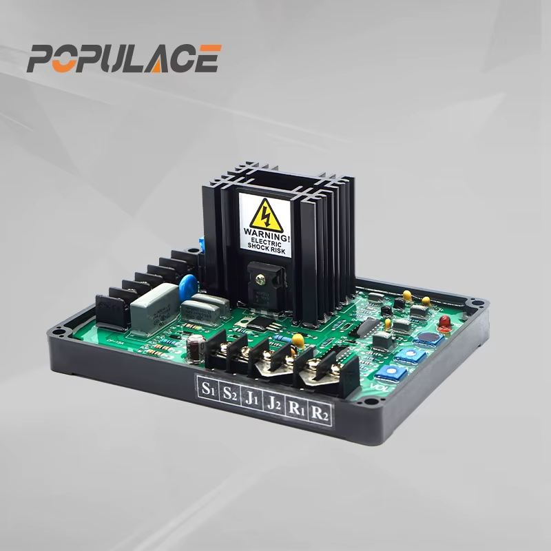
GAVR-20A: How to Wire and Set Up a 20A Generator AVR
A GAVR 20A is an automatic voltage regulator (AVR) used in compatible brushless generator systems to sense output voltage and control field excitation. For wholesalers, service teams, and private-label buyers, the important point is not simply finding a regulator with “20A” in its name. A safe replacement depends on the generator’s sensing circuit, excitation arrangement, supply range, terminal markings, and the exact regulator revision.
This guide explains a practical way to evaluate, wire, commission, and troubleshoot a GAVR 20A without assuming that one terminal layout fits every genset. Disconnect and lock out the generator before work. If the diagram, terminal labels, or test equipment are unavailable, stop and use a qualified generator technician.
What a GAVR 20A does in a generator
An avr automatic generator controller compares the sensed alternator voltage with its set point. When load changes pull voltage down, the regulator can increase field excitation; when voltage rises, it can reduce excitation. The result should be a steadier generator output, provided the alternator, sensing leads, rotating rectifier, exciter winding, engine speed, and AVR are all healthy.
“GAVR 20A” is commonly used as a model-family identifier in the replacement market. Listings may describe related units as self-excited, half-wave, or programmable, but buyers should treat those descriptions as starting points for verification. Read the label and matching wiring documentation for the exact unit in hand. Do not select a regulator based only on enclosure shape, connector count, or a 30 kva generator avr price comparison.
Compatibility checks before you buy or replace an AVR
Use a short receiving inspection checklist before approving a GAVR 20A for stock or installation:
- Generator type: confirm the alternator is brushless and identify whether its excitation system matches the regulator design.
- Sensing and supply: compare the required voltage-sensing and AVR power inputs with the generator schematic. Do not infer these values from the genset kVA rating alone.
- Field circuit: identify the terminals that go to the exciter field and verify polarity or terminal designations in the supplied diagram.
- Control functions: compare voltage adjust, stability, under-frequency protection, droop/parallel operation, and any DIP-switch settings needed for the application.
- Mechanical fit: inspect mounting holes, insulation condition, terminals, heat clearance, and cable strain relief.
For a product-family comparison, a lower-current model may be useful only when its wiring and electrical specification match the alternator. The internal catalog includes a GAVR-8A exciter control unit, the matched GAVR-20A generator AVR, and a GAVR-12A brushless AVR. Treat each page as a sourcing reference and confirm the final electrical match with the generator documentation.
GAVR 20A wiring: a safe field sequence
Wiring a GAVR 20A is a verification exercise, not a color-to-color exercise. Harness colors vary by generator builder and replacement part supplier. Follow this sequence instead:
- Isolate the set. Open the generator breaker, disable starting, disconnect battery starting power where required by site procedure, and prove the circuit is de-energized.
- Record the old regulator. Photograph terminal labels, write down wire identifiers, and compare the old unit’s diagram with the new regulator documentation. Mark every lead before removal.
- Inspect the alternator side. Check sensing leads, auxiliary winding leads, exciter-field leads, terminals, and insulation for looseness, overheating, corrosion, or rubbed conductors. Replacing the AVR will not repair a damaged exciter circuit.
- Mount the regulator. Use the intended mounting points, keep conductive debris away from the board, and maintain clearance around terminals and adjustment controls.
- Land wires by terminal function. Connect sensing, AVR supply, and field leads only to the functions named on the exact GAVR 20A diagram. Tighten terminals to the manufacturer’s stated practice and provide strain relief.
- Set controls conservatively. Before starting, place voltage and stability adjustments near the documented initial position. Do not turn all controls fully clockwise or fully counterclockwise.
- Commission with instruments. Start at no load, measure generator output with a suitable meter, let the engine reach rated speed, and adjust voltage gradually. Apply load in controlled steps while watching voltage stability and abnormal heating.
A generac generator regulator is not automatically interchangeable with a GAVR 20A just because both regulate generator voltage. OEM control logic, connector format, sensing method, and protective functions may differ. For mixed fleets, keep OEM part numbers and compatible aftermarket regulator records separate in the purchasing system.
Initial setup and adjustment
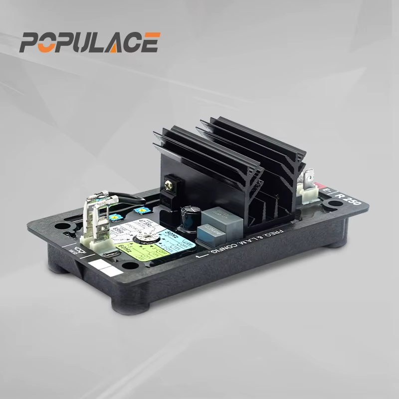
After the wiring passes inspection, set engine speed to the generator maker’s rated frequency before judging voltage performance. Frequency and voltage behavior are linked in many generator systems, so an engine-speed issue can look like a regulator issue. With the set stable at no load, adjust the voltage control slowly toward the specified output. Then add a representative load and observe the response.
If the output hunts or oscillates, return to the documentation and make small stability adjustments only after confirming wiring integrity and engine-speed stability. Do not use the AVR controls to hide a failing rectifier, loose sensing lead, poor ground connection, or overloaded generator. Record the final control positions, measured no-load voltage, loaded voltage, and test conditions for future service.
Troubleshooting a GAVR 20A installation
| Symptom | Check first | Practical next step |
|---|---|---|
| No voltage or very low voltage | Engine speed, residual magnetism, sensing/supply leads, field circuit, rotating diodes | Verify the alternator and wiring against its schematic before condemning the AVR. |
| Voltage too high | Voltage adjustment position, sensing connection, incorrect regulator configuration | Stop, confirm terminal functions and configuration, then recommission at a safe setting. |
| Voltage fluctuates | Engine governor stability, loose sensing connections, stability control, intermittent field path | Correct mechanical and wiring faults before making fine AVR adjustments. |
| AVR overheats or fails repeatedly | Field load, shorted wiring, ventilation, incorrect replacement selection | Inspect the alternator excitation circuit and validate compatibility before fitting another unit. |
How wholesale buyers should compare AVR offers
A low 30 kva generator avr price can be useful for initial screening, but it is not a technical specification. Ask suppliers for the exact model label, terminal diagram, revision information, packing method, lead time, and inspection process. For brand owners, request samples for a controlled bench or genset test before setting a production specification. A supplier focused on generator control components can help organize AVR, governor, actuator, and spare-parts sourcing, but the buyer should still maintain an approved compatibility matrix by alternator model.
For GAVR 20A stock planning, separate universal replacement demand from customer-specific applications. Label cartons with the confirmed model and revision, retain wiring documentation with the shipment, and build a return-analysis process around actual installation findings. This approach reduces avoidable returns caused by a mismatch rather than a defective regulator.
Key takeaway
A GAVR 20A can be an effective voltage-control replacement when it is selected and installed against the generator’s real wiring and excitation requirements. Verify the diagram, map terminal functions, set up with measured voltage and load, and troubleshoot the full alternator system before replacing another AVR. That disciplined process is safer for service teams and more defensible for wholesale purchasing decisions.






