
 EN
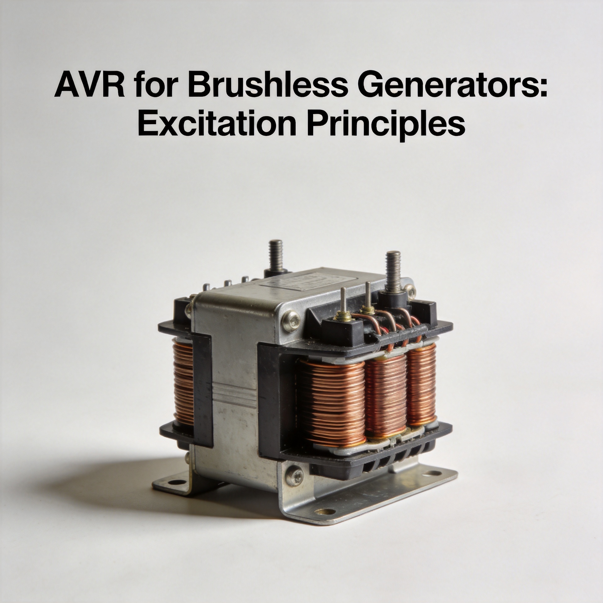
AVR for Brushless Generators: Excitation Principles
When a generator's output voltage drifts under load or oscillates during startup, the investigation typically traces back to the excitation circuit — and specifically to the automatic voltage regulator (AVR) that governs it. In brushless generator configurations, there are no brushes or slip rings to wear out, but the solid-state avr brushless generator control loop is the single point that determines whether output voltage holds within specification or breaks down under changing conditions.
How Brushless Excitation Works
A brushless generator eliminates the carbon brushes and slip rings used in older wound-rotor designs by placing the exciter and rotating rectifier directly on the rotor shaft. The AVR brushless generator excitation sequence operates as follows:
- The permanent magnet pilot exciter (PMG) or residual magnetism in the main stator provides an initial AC signal — typically 120–240V AC depending on the generator design.
- The automatic voltage regulator (AVR) receives this signal, rectifies it, and outputs a controlled DC current to the exciter field winding.
- The exciter field induces an AC voltage in the rotating exciter armature, rectified by the rotating rectifier assembly and fed as DC into the main rotor field.
- The main rotor field generates the terminal output voltage, which the AVR continuously senses and adjusts to hold output stable — typically within ±1% under steady-state conditions with 4% engine governing.
The avr brushless generator unit is the control loop closure point. Its sensing voltage range, response speed, and DC output current capacity all directly affect regulation quality. For wholesale buyers and brand merchants, these parameters — not just the price — determine whether a part will perform reliably after installation.
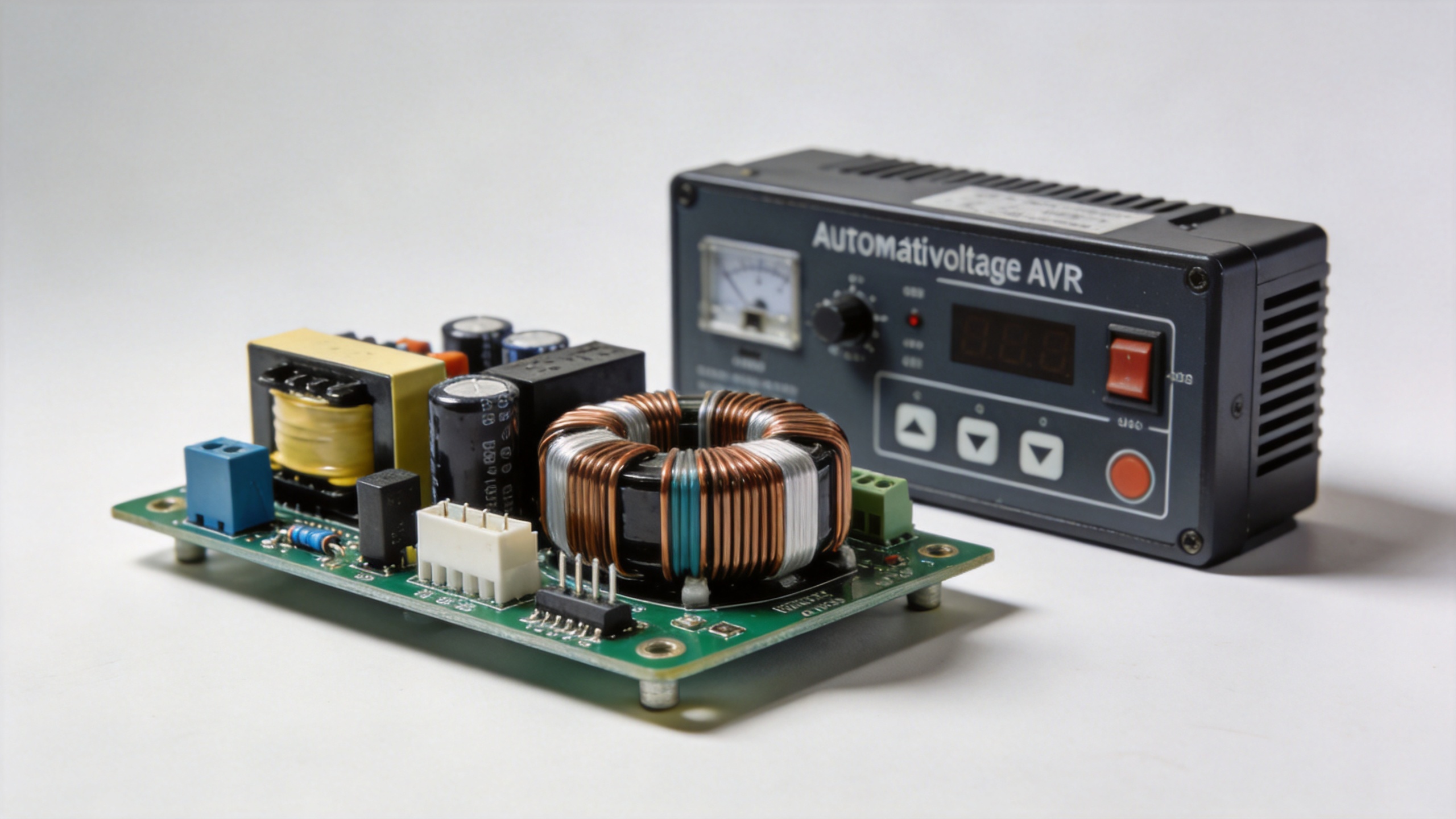
Common AVR Models and Their Applicable Power Ranges
The market for avr brushless generator components spans from small portable units to large industrial gensets. Matching the avr brushless generator to the application range is where most specification errors occur:
| Model | Sensing Input | Exciter Output | Typical Power Range | Notes |
|---|---|---|---|---|
| SX440 | 95–132V / 190–264V AC | 90V DC, 4A | 10–40 kVA | Single-phase sensing; common for mid-range diesel gensets |
| SX460 / AS440 | 85–132V / 170–264V AC | 90V DC, 4A | 10–80 kVA | SX460 superseded by AS440 (2-phase sensing); AS440 is the direct replacement in most applications |
| R120 | 85–135V / 170–270V AC | 120V DC, 4A | 15–100 kVA | Higher output voltage ceiling suits alternators with higher field requirements |
| Stamford MX341 2 | 95–132V / 190–264V AC | 150V DC, 4A | 25–150 kVA | stamford mx341 2-channel design; single and 3-phase sensing configurations |
| GAVR-8A / 12A | 85–140V AC universal | 8A or 12A DC | 3–15 kVA (5kw voltage regulator range) | Universal brushless avr; broad winding compatibility for smaller gensets |
| AVC63-4A | 100–120V AC | 63V DC, 4A | 5–40 kVA | avc63 4a: lower field voltage requirement; verify winding resistance before substitution |
If you are sourcing for a customer running a DSE 6020 deep sea controller on a multi-set installation, confirm whether the avr brushless generator accepts a remote voltage trim signal — not all models support this, which affects compatibility where the 6020 deep sea controller manages load sharing.
Procurement Considerations for Wholesalers and Brand Buyers
For distributors and brand merchants, sourcing an avr brushless generator component involves three compounding factors: compatibility coverage, service life, and replacement cost over the product lifecycle.
Compatibility coverage means understanding which alternator winding configurations and sensing voltage ranges a given AVR can serve. A supplier offering both model-specific brushless generator AVRs (R120, MX341) and universal types (GAVR-8A, GAVR-12A) lets you consolidate inventory while covering a wider installed base.
Service life in AVRs is primarily affected by operating temperature, input voltage transients, and the quality of the power transistor or TRIAC stage that drives the exciter field. Counterfeit or low-grade components in that output stage are the most common cause of premature failure in any avr brushless generator replacement scenario. Specification compliance on paper does not guarantee production consistency.
For a product like the R120 digital genset AVR or a universal brushless type like the GAVR-12A brushless AVR, consistent batch quality and pre-sales compatibility confirmation matter more than the first-order unit price. The GAVR-8A exciter control unit is a practical option for small brushless gensets in the 3–10 kW range, including the 5kw voltage regulator segment.
Installation and Common Fault Indicators
Wiring errors are the most preventable cause of AVR failure after installation. The exciter field terminals (F+ and F−) on any brushless generator AVR must be connected with polarity observed. Reversed polarity in most solid-state designs will not cause immediate component failure, but will prevent voltage from building and leave the AVR driving maximum output with no useful excitation. Verify the wiring diagram for the specific alternator model before installation — the generic avr brushless generator connection diagram may not match your alternator's terminal layout.
The most common faults in brushless AVR systems:
- No output voltage at no load: AVR failed, rotating rectifier diode open, or loss of residual magnetism. Test exciter field winding resistance first to eliminate the AVR as the primary cause.
- Hunting (oscillating voltage): Stability setting too low, winding resistance outside the avr brushless generator's designed range, or engine governor interaction. Adjust the stability potentiometer incrementally under load.
- Voltage collapses under load: AVR output current insufficient for the field demand — especially relevant when selecting a 5kw voltage regulator replacement or an avc63 4a for a specific alternator application.
- Component failure after 6–18 months: Thermal stress or voltage transients exceeding the AVR's input rating. Verify sensing input voltage under loaded conditions for the model in use.
Frequently Asked Questions
What does an AVR do in a brushless generator?
In a brushless generator, the AVR controls the DC current supplied to the exciter field, which regulates the main rotor field strength and the terminal output voltage. Without a functioning avr brushless generator control loop, output voltage varies with load changes rather than holding stable within specification.
Can a universal AVR replace a model-specific unit?
Often yes, provided the sensing voltage range and exciter output current rating match the alternator's winding requirements. GAVR-type avr brushless generator units are designed for broad compatibility, but winding resistance against the AVR's load specification should be confirmed before installation. For the stamford mx341 2-channel or avc63 4a applications, verify the alternator nameplate and wiring diagram before substituting.
Summary
The AVR is the control-loop element that makes brushless generator excitation work reliably. For buyers sourcing at scale — whether building a product line around GAVR-type universal avr brushless generator modules or stocking model-specific avr brushless generator units for a particular alternator brand — the key variables are sensing input range, exciter DC output current capacity, and consistent production quality across batches.






