
 EN
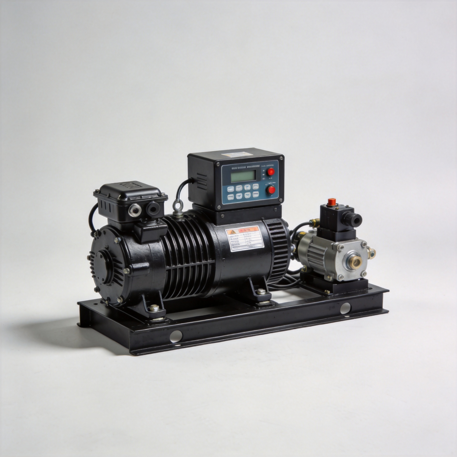
Speed Governor Control System: Components Overview
Work with diesel generators long enough and one pattern becomes clear: governor selection is not about picking the most recognized brand. It is about matching the control logic, sensing range, and actuator response to the specific engine variant and operating environment. Understanding that distinction is where a technical grasp of the speed governor control system starts.
This overview covers the hardware components that make up a diesel generator speed governor control system, the operating modes that govern single-unit and parallel configurations, and the calibration steps that technical procurement teams need to confirm before commissioning.
What Is a Speed Governor Control System?
A speed governor control system regulates diesel engine RPM by continuously measuring rotational speed and adjusting fuel delivery to maintain a target setpoint. In generator applications, maintaining stable speed translates directly to stable AC output frequency — typically 50 Hz or 60 Hz depending on the market. Even a few RPM of deviation under changing load conditions can cause frequency drift that trips sensitive equipment.
The system operates as a closed-loop feedback controller. Speed is measured, compared against a reference setpoint, and the difference — the error signal — drives a corrective output to the fuel control actuator. Electronic governor controllers execute this loop digitally; mechanical governors use centrifugal flyweights and spring-loaded linkages to achieve the same result through a purely physical mechanism.
Core Components of a Speed Governor Control System
Speed Sensing Element
The speed sensor converts engine rotational speed into an electrical signal the controller can process. Magnetic pickup sensors are the most common type for diesel generators: as gear teeth on the flywheel pass the sensor tip, the sensor generates a pulsed AC voltage. The controller counts pulse frequency to calculate RPM in real time.
Sensor placement matters in practice. Most installations position the magnetic pickup at the free end of the engine, targeting the ring gear or a dedicated speed gear. If your application runs at variable ambient temperatures or under high vibration, verify the sensor's rated operating temperature and mounting gap specification — the catalog rating will not flag those variables for you automatically.
Electronic Control Unit
The electronic control unit is the processing center of the speed governor control system. It receives the speed signal, executes the PID (proportional-integral-derivative) control algorithm, and generates an output signal to drive the actuator. Gain parameters — proportional gain, integral time, derivative time — are adjusted during commissioning to match engine inertia and load characteristics.
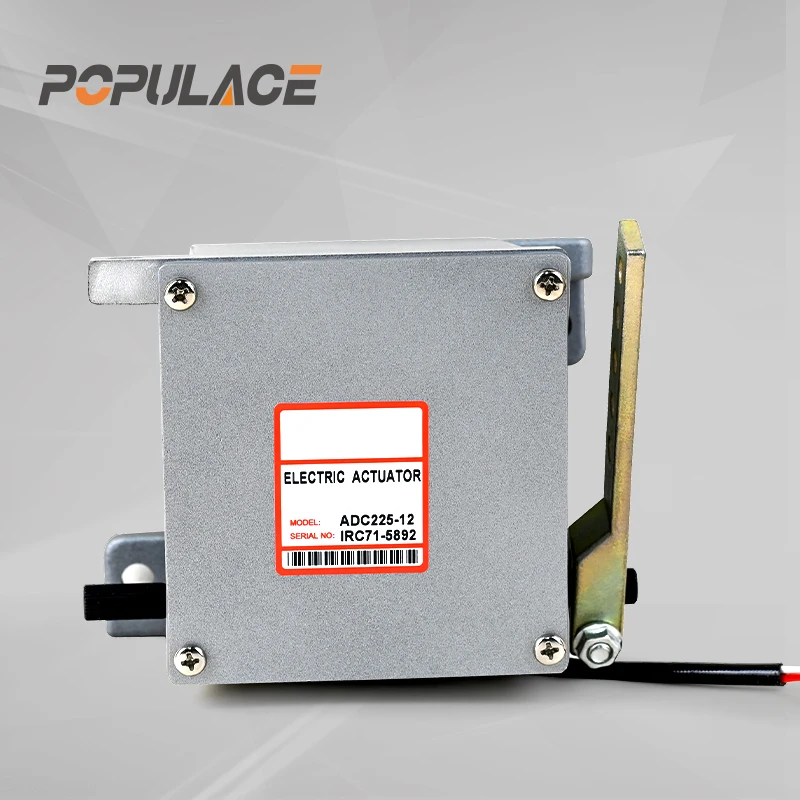
Electronic controllers like the S6700H Governor Speed Controller Diesel Engine Generator Speed Control Unit and the ESD5500E Speed Governor Generator Speed Control Unit offer adjustable droop settings and isochronous mode selection, making them suitable for both standalone gensets and parallel configurations. Brands such as Woodward and Barber Colman established many of the interface conventions that modern electronic controllers still follow — the barber colman electronic governor lineage in particular shaped connector layouts and control signal standards that remain in widespread use. Aftermarket-compatible units and aftermarket speed governor replacements now cover most of these interface types, giving procurement teams more sourcing flexibility without sacrificing control loop performance.
Actuator
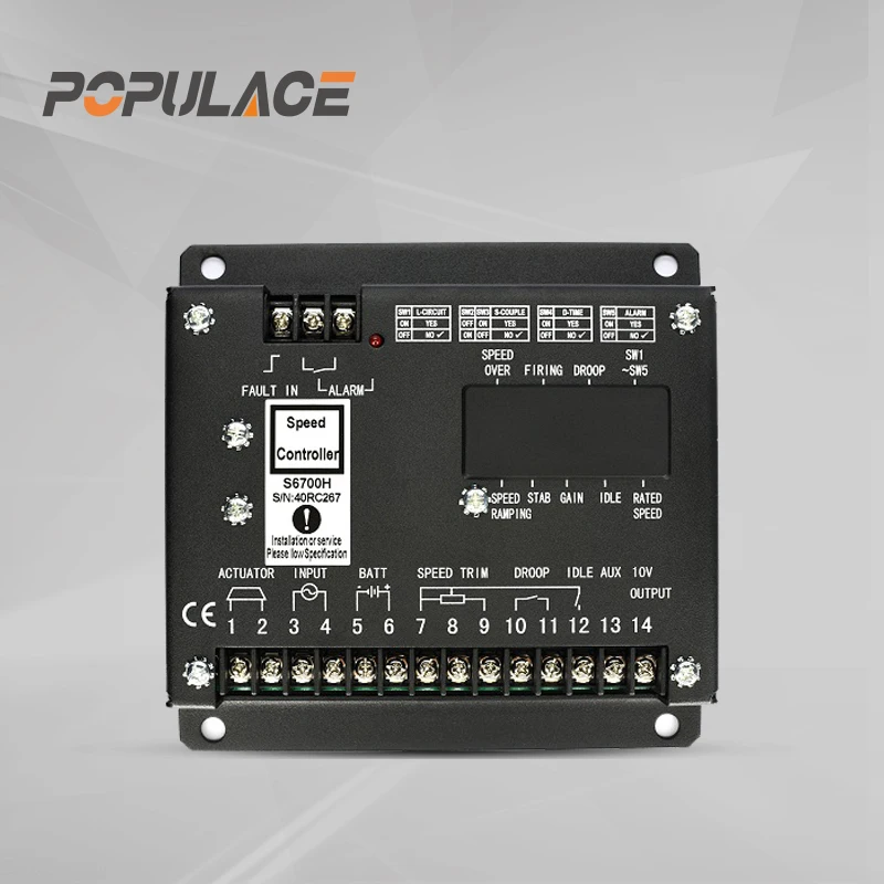
The actuator translates the controller's electrical output signal into physical fuel rack movement on the injection pump. Two main types are used in diesel generator applications: proportional actuators and on-off actuators. Proportional actuators provide continuous, variable-position output proportional to the control signal — the preferred type for precise isochronous control. On-off types are mechanically simpler and used in less demanding applications.
Actuator compatibility tends to get underestimated in the sourcing process. Early in the selection cycle, buyers typically focus on voltage supply and coil resistance. After a failed installation, the focus shifts to shaft interface dimensions, connector pinout, and response curve matching — compatibility factors the specification sheet will not surface independently. The POPULACE External Actuator ADC120/ADC175/ADC225 range covers 12V and 24V supply options with multiple torque ratings, addressing the installation variation common across diesel generator fleets.
Mechanical vs. Electronic Governors
Mechanical governors use centrifugal flyweights rotating with the engine shaft. As speed increases, flyweights move outward against a spring, physically repositioning a fuel control linkage. They require no electrical power and are inherently self-contained — a genuine advantage in environments where electrical system reliability is a concern. The trade-off is limited adjustment range, no remote speed setting capability, and slower transient response compared to electronic alternatives.
Electronic governors execute the same control function in firmware, replacing the mechanical linkage with sensor, controller, and actuator stages. The result is tighter speed regulation, faster transient recovery, and adjustable parameters that can be calibrated on-site. Digital controllers designed for the same interface as legacy Woodward or str governor generator systems allow direct replacement without engine-side mechanical changes.
For industrial generators above 100 kW, electronic governors are now the standard configuration. Mechanical governors remain in service on older units and some smaller prime movers where operational simplicity outweighs the precision advantages of electronic control.
Isochronous vs. Droop Mode: Single-Unit and Parallel Operation
Governor operating mode is one of the more consequential parameters in a multi-generator system. Getting this wrong produces instability that is often misdiagnosed as a hardware fault.
Isochronous mode maintains constant engine speed regardless of load. The governor continuously corrects to hold the speed setpoint exactly, with zero steady-state speed error. This is the appropriate mode for a single generator supplying an isolated load, or for one designated swing machine in a paralleled islanded system.
Droop mode (also called proportional speed control) allows engine speed to decrease slightly as load increases. The relationship is linear: a 5% droop setting means speed drops 5% from no-load to full-load rated speed. When two or more generators operate in parallel, droop mode allows each machine to share load in proportion to its droop curve — without hunting or circulating currents between units. Running two paralleled generators in isochronous mode causes them to compete for speed control, producing system instability.
The practical working rule: isochronous for single-unit operation in island mode; droop for parallel operation or grid connection. Most electronic controller units, including the S6700H and ESD5500E, provide both modes with field-selectable switching.
Industrial Generator vs. Mobile Power Station Requirements
Industrial generators in fixed installations — data centers, hospitals, manufacturing facilities — operate under relatively predictable load profiles with stable ambient conditions. Governor parameter tuning for these applications typically prioritizes frequency stability over transient response speed.
Mobile power stations present a different set of constraints. Load steps are abrupt and less predictable. Ambient temperature ranges are wider. Vibration levels are higher. Governor systems on mobile gensets generally require faster actuator response, higher proportional gain settings, and more robust sensor mounting. Supply voltage tolerance is also broader in mobile configurations, where battery system voltage fluctuates under starting loads.
Calibration and Adjustment: A Practical Overview
Governor calibration starts with confirming the speed reference: the target no-load frequency and the droop percentage, if applicable. For a 50 Hz system running at 1500 RPM on a 4-pole alternator, the no-load speed setpoint is set slightly above 1500 RPM to account for rated-load droop.
Key adjustment steps include: setting the speed trim potentiometer to establish base RPM, adjusting gain to eliminate hunting without over-damping transient recovery, and verifying stability at no-load, 50% load, and full load. If the engine hunts — oscillates in speed without settling — proportional gain is too high; reduce it in measured increments and retest. If load steps produce large frequency dips with slow recovery, increasing the integral gain generally helps.
Calibration records should document the final potentiometer settings and load test results. For technical procurement teams evaluating a speed governor control system replacement, confirming that the replacement unit's adjustment range covers the original calibration values prevents a commissioning round that could have been resolved at the specification stage.
For wholesale and sourcing inquiries on speed governor control units and actuator components, contact Populace Electronic Co., Ltd. at kygenpower.com or reach the technical team at [email protected].






