
 EN
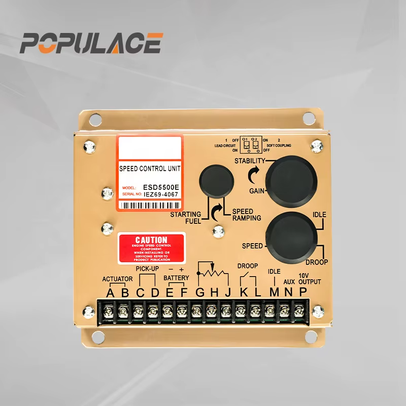
Speed Control Unit Esd5500E: Features and Selection Guide
Choosing the right speed control unit for a diesel engine generator looks like a straightforward task — until you are standing in front of a machine that is hunting or surging under load. Price is the starting point, but what usually determines whether the part actually performs is whether the governor's response curve, operating mode, and actuator interface match your specific engine setup. The speed control unit ESD5500E is among the most widely sourced electronic governors in the industrial generator segment. This guide covers its core features, mode selection logic, and the checks worth completing before you order.
What Is the Speed Control Unit ESD5500E?
The speed control unit ESD5500E is an all-electronic PID (Proportional-Integral-Derivative) device built to regulate diesel engine speed in response to transient load changes. Where mechanical governors rely on flyweights and springs, this unit uses a magnetic speed sensor signal and a proportional electric actuator to hold the desired RPM with more precision and quicker response.
It runs on 12 or 24 VDC and covers a speed sensor frequency range of 1,000 to 7,500 Hz — a range wide enough for most diesel engines used in fixed gensets and mobile power stations. The design allows installation in a control cabinet or directly on the engine enclosure, so it fits industrial settings where temperature variation and vibration are ongoing conditions.
Key Technical Specifications
The speed control unit ESD5500E delivers the following performance parameters:
- Power supply: 12 or 24 VDC
- Speed sensor frequency range: 1,000–7,500 Hz
- Isochronous steady-state stability: ±0.25% or betterDroop range: 1–5% regulation
- Gain adjustment range: 33:1
- Actuator output switching frequency: ~500 Hz
- Actuator current range: 0.5–2.5 Amps
- Operating temperature: -40°C to +85°C
- Relative humidity: Up to 95%
The -40°C to +85°C temperature range and 95% humidity tolerance mean the speed control unit ESD5500E works in both indoor control rooms and exposed outdoor generator enclosures across a wide range of deployment climates.

Operating Modes: Isochronous vs. Droop
This governor supports three modes: isochronous, droop, and variable speed.
Isochronous mode holds engine speed constant regardless of how load changes. At ±0.25% steady-state stability, it works well for single-generator setups where frequency has to stay tight — applications powering sensitive electronics or communication systems, for instance.
Droop mode lets engine speed fall proportionally as load increases, with a range of 1–5% regulation. The common use case is parallel generator operation. Running two or more gensets in isochronous mode without a load-sharing controller causes them to fight each other for load; droop gives each machine the speed offset it needs to share load proportionally and stay stable.
Variable speed mode lets an operator adjust engine speed remotely using an external potentiometer. Pumping stations and compressors are typical applications where output demand shifts in a predictable way and the operator needs RPM control without touching the governor directly.
Application Scenarios: Industrial Gensets vs. Mobile Power Stations
The right mode for the speed control unit ESD5500E depends on how and where the generator is used. Fixed industrial gensets have predictable load profiles and get calibrated once at commissioning — isochronous mode is the standard choice there. Mobile power stations are a different story: the generator may move across sites with different load types and no specialist to recalibrate it. The 33:1 gain adjustment range and variable speed capability give field operators enough tuning headroom to adapt without swapping the governor.
For stable system output, the governor works alongside the AVR. Pairing this unit with a compatible AVR — such as the MX321 (avr mx 321) or the Stamford MX341 (avr stamford mx341 / stamford avr mx321) — keeps both speed and voltage within tolerance through load changes. Two overlooked contributors to instability are a generator trickle charger that is undersized for standby duty and an AVR with the wrong sensing voltage input — both of which often get misdiagnosed as governor problems.
Selection Criteria: What to Confirm Before You Order
Specifying engine brand alone rather than the exact model and serial range is one of the more common ordering errors with speed governors, and it leads to parts that arrive with the wrong actuator interface. Before placing a speed control unit ESD5500E order, these are the checks worth completing:
- Engine model and actuator type: Compatible with all GAC proportional actuators except the ACB2000. When the ADC100 series actuator is already installed, the available droop range will be narrower because of its lower current draw.
- Speed sensor signal level: The minimum requirement is 1 VAC RMS from the magnetic sensor during cranking; 3 VAC RMS or greater is recommended at governed speed. A sensor that falls short will produce erratic speed control.
- Battery supply voltage: The speed control unit ESD5500E accommodates both 12V and 24V systems, but the wiring differs between them — confirm before specifying the harness.
- Required operating mode: Single-unit operation maps to isochronous. Parallel operation requires droop. Remote speed trimming calls for variable speed mode.
- Enclosure environment: Verify that the enclosure maintains airflow sufficient to stay within the -40°C to +85°C range under continuous duty.
Calibration and Adjustment Steps
Speed control unit ESD5500E calibration starts with all adjustment potentiometers at midpoint. For the speed sensor, back out 3/4 turn after the tip touches the ring gear tooth — that establishes the recommended air gap (0.020 in. minimum). Confirm the sensor reads at least 1 VAC RMS during cranking; a signal below that threshold triggers the fail-safe and cuts fuel delivery.
Start the gain adjustment at midpoint, then move incrementally while watching engine response through load transitions. Slow periodic instability at below 3 Hz points to gain being too high — reduce it. Fast instability tracking individual engine firings is handled through the derivative switch rather than the gain adjustment. When trying to restore stability, move the stability control counterclockwise first before making other changes.
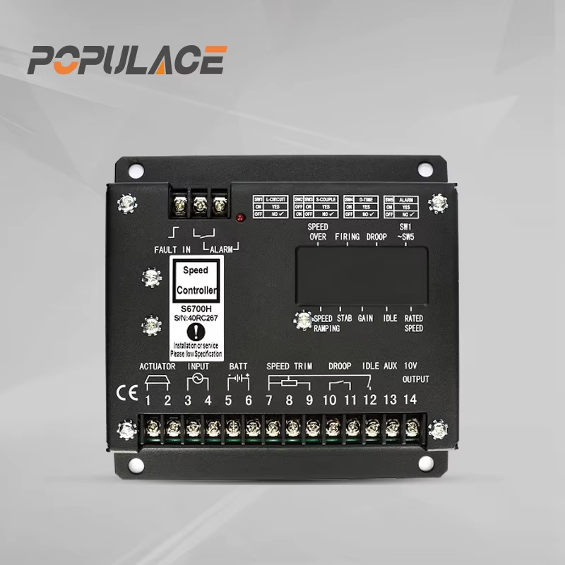
Product Options from KYGEN Power
KYGEN Power supplies the speed control unit ESD5500E factory-direct under the Populace brand for wholesale and B2B buyers who need consistent batch quality and predictable lead times. For installations where different actuator current characteristics are required, the S6700H Governor Speed Controller is available as an alternative in the same product range.
Buyers who need the actuator as well can source external actuators (ADC120, ADC175, ADC225) in 12V and 24V versions from the same supplier, which removes the coordination step of sourcing governor and actuator through different channels.
Speed Control Unit ESD5500E: Summary Checklist
Before finalizing a speed control unit ESD5500E order, confirm:
- Engine model and actuator compatibility — not just the engine brand
- Speed sensor output reaches the 1 VAC RMS minimum during cranking
- System battery voltage: 12V or 24V
- Operating mode: isochronous for single units, droop for parallel gensets, variable speed for remotely trimmed applications
- Enclosure conditions stay within the -40°C to +85°C operating range
- Whether the actuator also needs to be sourced
- AVR model compatibility — MX321 or MX341 for stable voltage alongside governed speed
Whether sourcing the speed control unit ESD5500E as a direct field replacement or building inventory for a maintenance program, confirming actuator interface, sensor signal level, and operating mode covers the main compatibility issues that show up at installation.





