
 EN
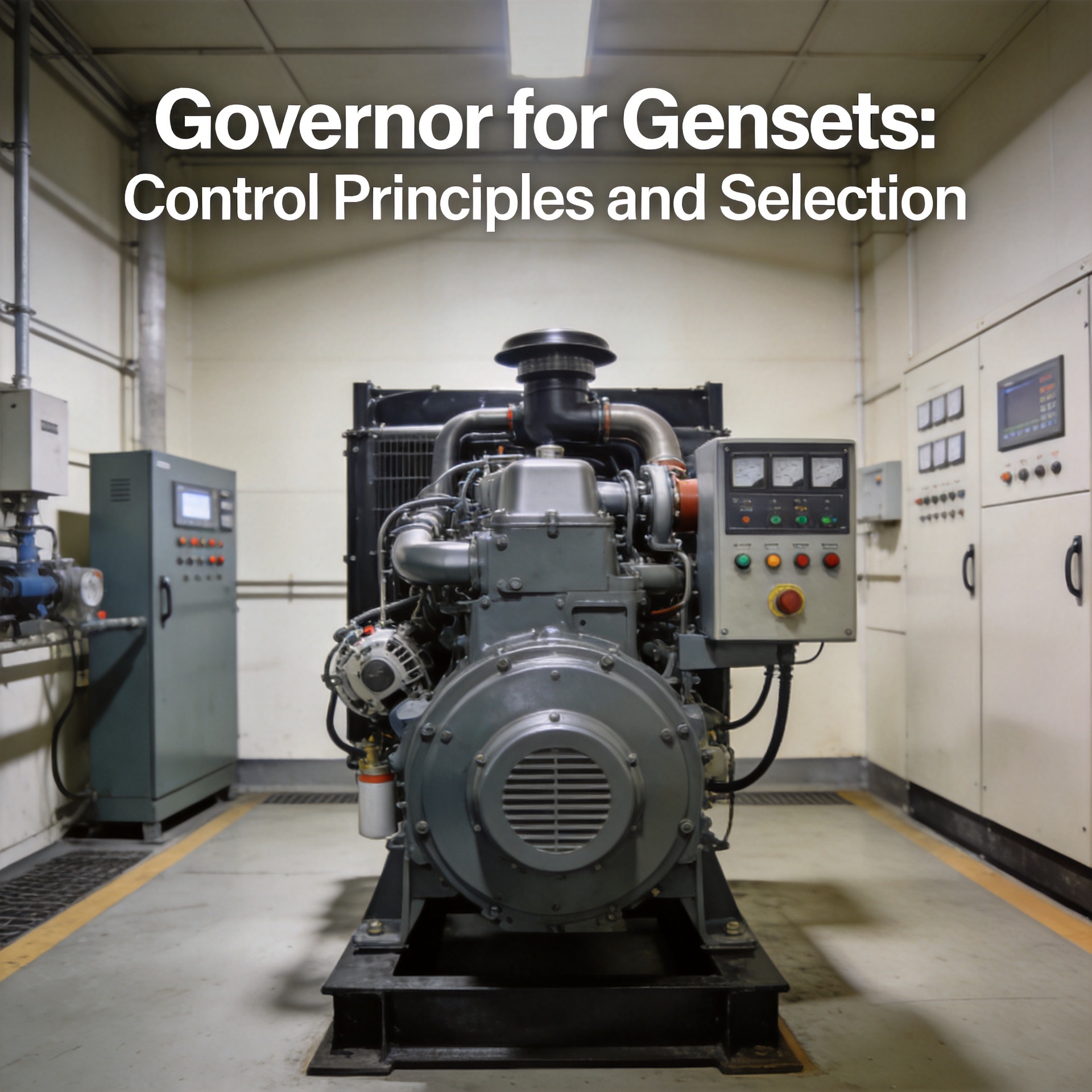
Governor for Gensets: Control Principles and Selection
Choosing the right governor genset component is one of those decisions that looks simple until it isn't. Buyers routinely order a governor genset replacement by engine brand alone, only to find the unit hunts under load or loses frequency stability when paralleled. A governor genset application requires matching the control type, actuator interface, and operating mode to the actual engine and load — not just buying the closest model number available.
What a Governor Does in a Generator Set
The governor in a diesel generator set maintains engine speed by controlling the fuel rack position. When connected load increases, RPM drops; the governor senses this deviation and injects more fuel to return to the setpoint. When load decreases, it pulls fuel back. This continuous feedback is what holds output frequency at 50 Hz or 60 Hz regardless of load swings.
Governor genset performance is classified under international standards: Class 1 allows ±0.25% steady-state speed variation, Class 2 allows ±0.5%. For industrial applications where the diesel engine control module must coordinate with AVR systems, Class 1 is typically the baseline requirement.
Mechanical vs. Electronic Governors
Two governor types cover most governor genset applications today. Understanding the difference between them is the foundation of any informed governor genset selection decision — and it goes beyond price.
Mechanical Governors
Mechanical governors regulate engine speed through centrifugal flyweights. As RPM rises, flyweight movement reduces fuel delivery via a mechanical linkage; as RPM drops, the linkage opens. No external power or sensors are required — the system is entirely self-contained.
For legacy diesel gensets in remote or low-maintenance environments, a mechanical unit is often the most cost-effective governor genset solution. Speed regulation accuracy is the main limitation: mechanical governors typically cannot hold Class 1 tolerance under dynamic load conditions.
Electronic Governors
Electronic governors use a magnetic pickup sensor combined with an electronic control unit that drives an electro-hydraulic actuator. Response time is significantly faster than any mechanical system, making electronic governor genset configurations the standard for:
- Industrial generator sets with Class 1 frequency requirements
- Natural gas engines, which are more sensitive to governor response speed
- Parallel genset systems where synchronization accuracy matters
- Generator sets paired with digital AVR systems requiring tight frequency-voltage coordination
Most electronic governor genset units allow adjustment of gain, stability, and droop percentage, enabling fine-tuning to specific engine and load characteristics. The S6700H Governor Speed Controller Diesel Engine Generator Speed Control Unit is designed for this range of diesel governor genset applications, covering standard electronic speed control requirements.
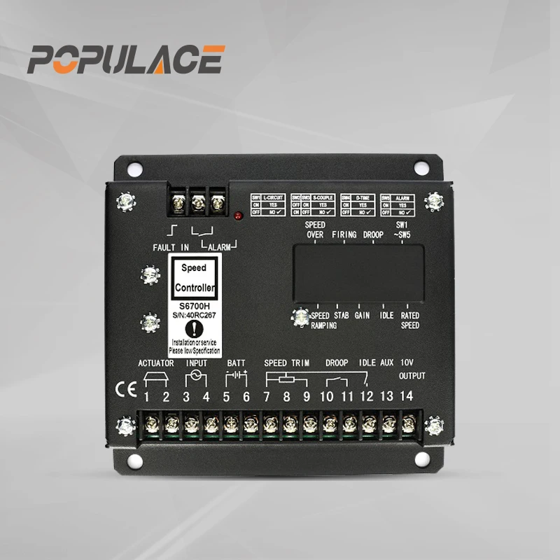
The ESD5500E Speed Governor Generator Speed Control Unit is another widely used governor genset control option, compatible with standard electro-hydraulic actuator configurations across a broad range of diesel engines.
Industrial Gensets vs. Mobile Power Stations
Governor genset requirements differ significantly between stationary and mobile applications.
Stationary industrial gensets run in predictable standby cycles with relatively stable load profiles. A standard-response electronic governor genset with a medium-duty actuator handles most scenarios well.
Mobile power stations face vibration, temperature cycling, and unpredictable load swings. For a governor genset in this environment, actuator durability and calibration stability are critical. The POPULACE External Actuator ADC120/ADC175/ADC225 provides 12V and 24V options in different stroke and force ratings, offering compatibility for various generator governor applications.
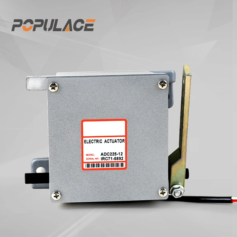
When evaluating a smart gen controller that includes built-in governor logic, confirm whether it interfaces with an external actuator or uses integrated electronic injection control. Interface mismatch between controller and actuator is a common and avoidable failure mode in governor genset installations.
Isochronous Mode vs. Droop Mode
Governor genset operating mode is one of the most consequential selection parameters, especially for parallel applications.
Isochronous (Constant Speed) Mode
In isochronous mode, the governor maintains a fixed engine speed regardless of load change. This is the correct governor genset mode for a single unit operating in isolation or as the sole source in an island (off-grid) system. Frequency remains constant and there is no ambiguity about which machine controls the bus.
Droop (Speed Variation) Mode
Droop mode allows engine speed to fall slightly as load increases — typically 4-5% from no-load to full load. When two or more governor genset units are paralleled, operating all in isochronous mode creates instability: each unit tries to control frequency independently, causing circulating current and load oscillation. Droop mode introduces a natural load-sharing mechanism that distributes load proportionally across paralleled units.
A 5% droop setting means the generator drops approximately 2.5 Hz (50 Hz system) between no-load and full load. For grid-parallel governor genset applications, droop mode is mandatory on the generator side — the grid dictates frequency and the genset governor must accommodate that. When using a generac generator control panel or any digital paralleling controller, governor mode is typically configurable through the panel interface.
Selection Criteria
When evaluating a governor genset solution, work through these parameters systematically:
- Engine compatibility: Match the governor type to the fuel injection system. Mechanical injection engines use external actuator-based governor genset controllers; common rail engines typically use integrated ECU control.
- Actuator interface: Confirm actuator voltage (12V or 24V), stroke, and force rating against the engine's fuel rack requirements.
- Operating mode: Single-machine standby needs isochronous. Parallel governor genset systems require droop or active load-sharing control.
- Response class: Class 1 for sensitive loads; Class 2 for standard industrial backup.
- Environment: Mobile and outdoor installations require sealed, vibration-resistant actuators and a wider operating temperature range.
Basic Calibration Steps
For procurement teams overseeing governor genset commissioning, a working knowledge of governor genset calibration steps helps verify correct setup without relying entirely on on-site specialists.
- No-load speed set: With engine running and no load, adjust the speed reference until the engine reaches rated no-load RPM (e.g., 1503-1505 RPM for 50 Hz governor genset applications).
- Stability adjustment: If the engine hunts at no load, reduce the gain potentiometer until oscillation stops. Excessive gain causes hunting; insufficient gain slows load response.
- Droop setting: For parallel governor genset applications, set droop as required (typically 4-5%). Confirm no-load and full-load RPM against specification.
- Load step test: Apply a sudden 50-100% load step and verify frequency recovery within 2-3 seconds without overshoot or sustained oscillation.
- Lock-down: After confirming stable operation, secure adjustment potentiometers against accidental de-tuning.
Summary
A governor genset selection that accounts for engine compatibility, actuator interface, operating mode, and performance class will consistently outperform one made on model number alone. Electronic governor genset units now cover most replacement and new-installation scenarios, with adjustable gain and droop settings that allow calibration to specific engine behavior. Treating compatibility verification and calibration as part of procurement — not an afterthought — is what separates reliable long-term genset operation from avoidable field problems.






