
 EN

Genset Speed Controller: Electronic vs Mechanical
A genset speed controller is the part of the governing system that keeps a diesel engine close to its intended speed as load changes. Because alternator frequency follows engine speed, a poor speed-control decision can show up as unstable frequency, slow recovery, hunting, or awkward load sharing. For a technical buyer, the useful question is not simply “electronic or mechanical?” It is which control method matches the engine, actuator, duty cycle, and operating mode.
This comparison is written from a replacement-parts and commissioning perspective. Start with the engine’s existing governor arrangement, then confirm the actuator, pickup signal, wiring, and setpoint requirements before selecting any genset speed controller.
What a genset speed controller does
The controller compares actual engine speed with a target speed and changes fuel delivery through the governor mechanism or an electric actuator. On a 50 Hz set, the target is commonly associated with 1,500 rpm for a four-pole alternator; on a 60 Hz set, it is commonly associated with 1,800 rpm. Those figures describe the speed-to-frequency relationship, not a universal commissioning instruction. The correct rated speed must be taken from the engine and alternator documentation.
A mechanical governor performs this feedback mechanically, typically through flyweights and springs. An electronic genset speed controller uses an electrical speed signal, a control board, and an actuator. Both can regulate speed; their differences become clearer when load moves quickly or when several sets must share load.
Mechanical governor: simple feedback at the engine
Mechanical governors are valued for their direct construction and independence from a separate control board. As engine speed rises, centrifugal force moves the flyweights and reduces fuel; as speed falls, spring force increases fuel. This arrangement can be practical for steady-duty engines, basic standby units, or applications where the original engine was designed around a mechanical governor.
The trade-off is adjustment range and response flexibility. Spring tension, linkage friction, wear, and actuator travel all affect behavior. A mechanical system may hold a serviceable speed under a stable load yet show more visible frequency movement during a step load than a well-matched electronic system. That is not a defect by itself; it is a question of the required regulation and the condition of the complete fuel-control mechanism.
Electronic governor: signal-based control for changing loads
An electronic genset speed controller reads engine speed, compares it with the selected reference, and commands an actuator to adjust fuel. Its main advantage is tunability: the technician can set response-related parameters within the manufacturer’s procedure rather than relying only on springs and linkages. That can make electronic control a strong fit for industrial sets with frequent load steps, mobile power units with variable demand, and installations that need coordinated control.
It also introduces dependencies. The speed sensor signal, controller supply, grounding, shielded wiring, actuator compatibility, and parameter settings all matter. A board cannot compensate for a sticking fuel rack, weak actuator, incorrect pickup gap, or air/fuel issue. During replacement, compare the whole governing loop instead of ordering a controller solely because its connector or product name looks familiar.
Industrial and mobile applications need different priorities
Industrial generator installations often prioritize predictable recovery, repeatable tuning, and integration with a dg set control panel. The panel may coordinate starts, alarms, synchronizing, or load-sharing logic, while the speed governor handles engine speed. Keep those responsibilities separate during troubleshooting: a panel alarm is not automatically a governor fault, and a governor change can affect the behavior that the panel observes.
Mobile power stations usually face vibration, varying ambient conditions, cable handling, and abrupt load changes. Here, installation quality can be as important as controller type. Protect connectors, verify grounds, route pickup wiring away from noise sources where the manufacturer requires it, and document the final setting. A generac control panel or any other branded controller should be identified by its actual interface requirements; brand name alone does not establish governor compatibility.
Isochronous versus droop operation
Control mode affects selection and adjustment. In isochronous mode, the governor attempts to maintain a constant target speed and therefore constant frequency as load changes. This is often useful for a single genset supplying an isolated load. In droop mode, the speed reference is allowed to decrease as load increases. That intentional slope can help parallel units share load when the overall system is configured for it.
Do not treat droop as a universal substitute for load sharing or isochronous as a universal parallel setting. Parallel systems depend on the complete control architecture, including synchronizing and load-sharing equipment. Follow the engine, governor, alternator, and switchgear documentation for the approved mode and adjustment sequence.
How to compare controller options without chasing a label
- Match the input: confirm magnetic pickup or other speed-signal type, expected signal condition, and wiring arrangement.
- Match the output: verify the controller is intended for the fitted actuator and its electrical characteristics.
- Match the application: distinguish steady single-set duty from variable-load or paralleled operation.
- Match the service plan: make sure a technician can access the required documentation and adjustment process.
- Compare total fit, not just price: the lowest-cost board can create downtime if its interfaces do not match the engine.
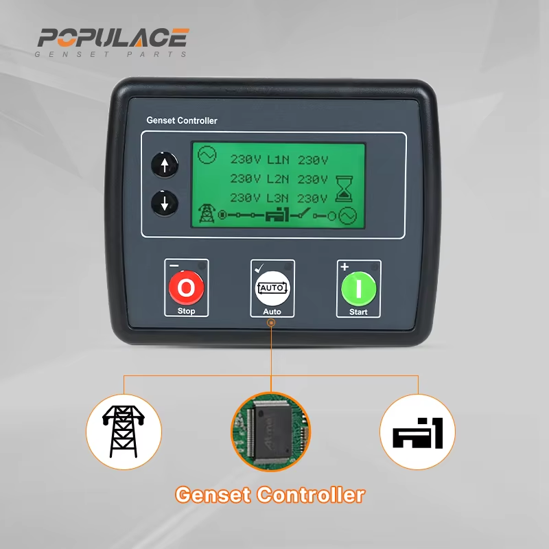
For example, the confirmed product catalog includes the S6700H Governor Speed Controller Diesel Engine Generator Speed Control Unit and the ESD5500E Speed Governor Generator Speed Control Unit. Treat these as product options to evaluate against the engine’s confirmed governing-loop requirements, not as interchangeable replacements. If a site also needs start/stop and alarm functions, the cataloged POPULACE DSE3110 Generator Auto Start Control Module belongs to the control-panel side of the system and should be assessed separately.
A safe adjustment and calibration workflow
- Read the applicable engine, governor, actuator, and controller documentation before changing settings.
- Inspect mechanical linkage, fuel-system condition, actuator movement, connectors, grounds, and the speed-sensing path.
- Confirm rated speed and the intended isochronous or droop mode for the site.
- Start with the manufacturer’s baseline settings; make one small change at a time and record it.
- Observe no-load stability, then apply controlled load changes only under qualified-site procedures.
- Stop and investigate persistent hunting rather than repeatedly increasing gain or sensitivity.
A speed controller cummins search should follow the same discipline: confirm the engine model, existing actuator and pickup arrangement, and approved replacement information. Compatibility is a documented system question, not a keyword match.
Make the choice around the operating system
A mechanical governor can remain the sensible solution for a simple, stable-duty engine. An electronic genset speed controller is often the more adaptable choice where transient response, repeatable adjustment, or coordinated operation matters. In either case, selection begins with verified compatibility and ends with controlled commissioning. That approach protects frequency quality, avoids unnecessary board swaps, and gives procurement teams a clearer basis for comparing options.





