
 EN
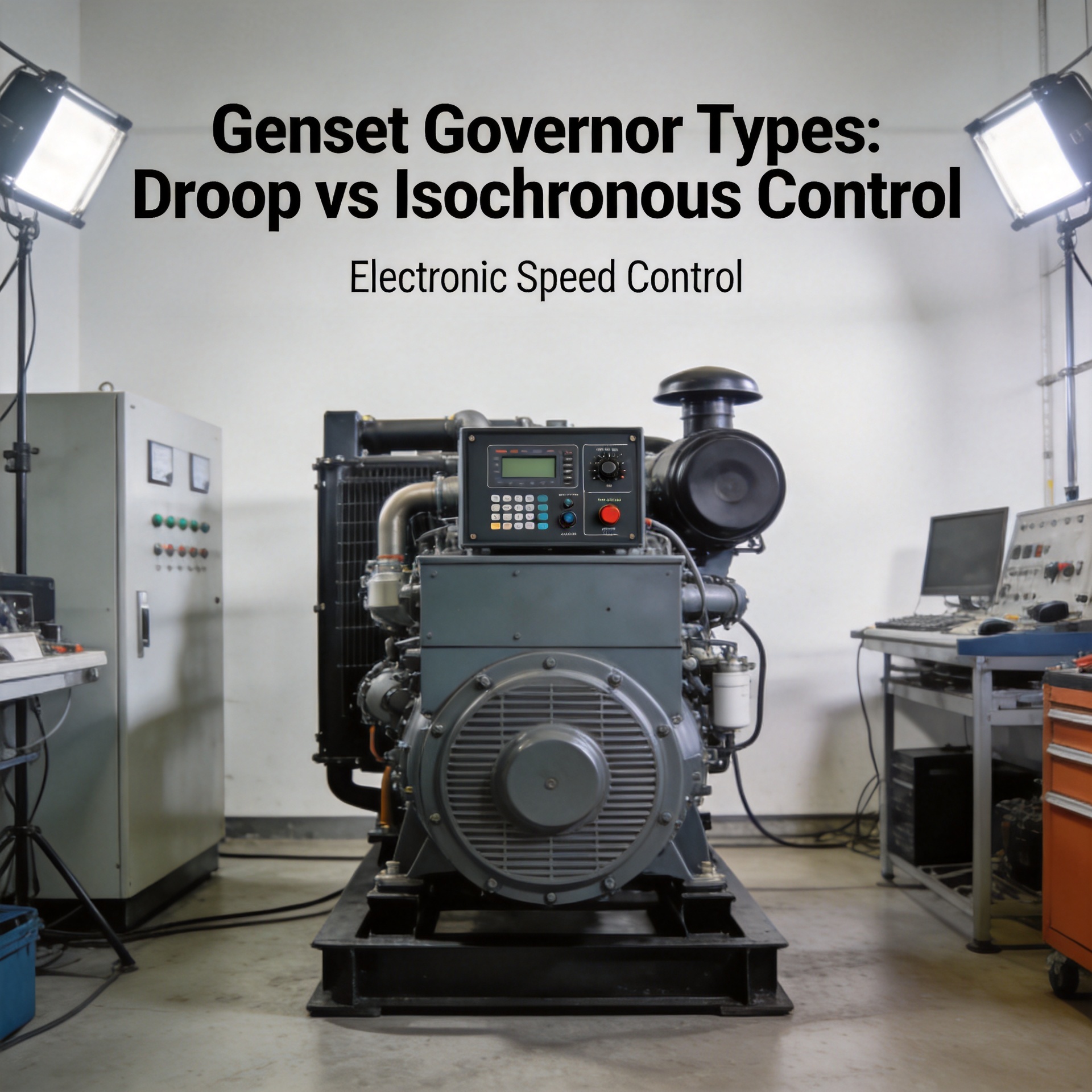
Genset Governor Types: Droop vs Isochronous Control
When evaluating genset governor types for an industrial installation or mobile power station, the first question is rarely "mechanical or electronic?" — it is "single-unit or parallel operation?" Because that decision dictates whether the application calls for droop control, isochronous control, or a combination of both. As a technical consultant specializing in generator control components, this distinction accounts for the majority of governor mismatches I encounter in the field.
What a Genset Governor Controls
A governor regulates diesel engine speed by modulating fuel delivery in response to load changes. When load increases, engine RPM tends to fall; the governor detects the deviation and opens the fuel rack to restore the set point. The speed-to-frequency relationship is fixed by alternator pole count: for a 4-pole machine at 50 Hz, the engine runs at 1500 RPM; at 60 Hz, 1800 RPM. The governor's job is to hold that RPM — or allow it to vary in a controlled way — as load fluctuates.
That basic function is common to all genset governor types. The real distinction is how tightly the governor holds speed under load, and how it behaves when multiple generators share a common bus.
Mechanical vs Electronic Governor Mechanisms
Older and smaller gensets use mechanical governors, where centrifugal flyweights sense speed changes and a spring-and-lever linkage adjusts the fuel injection pump. Response is inherently analog — proportional to the speed deviation — but limited in precision and adjustment range.
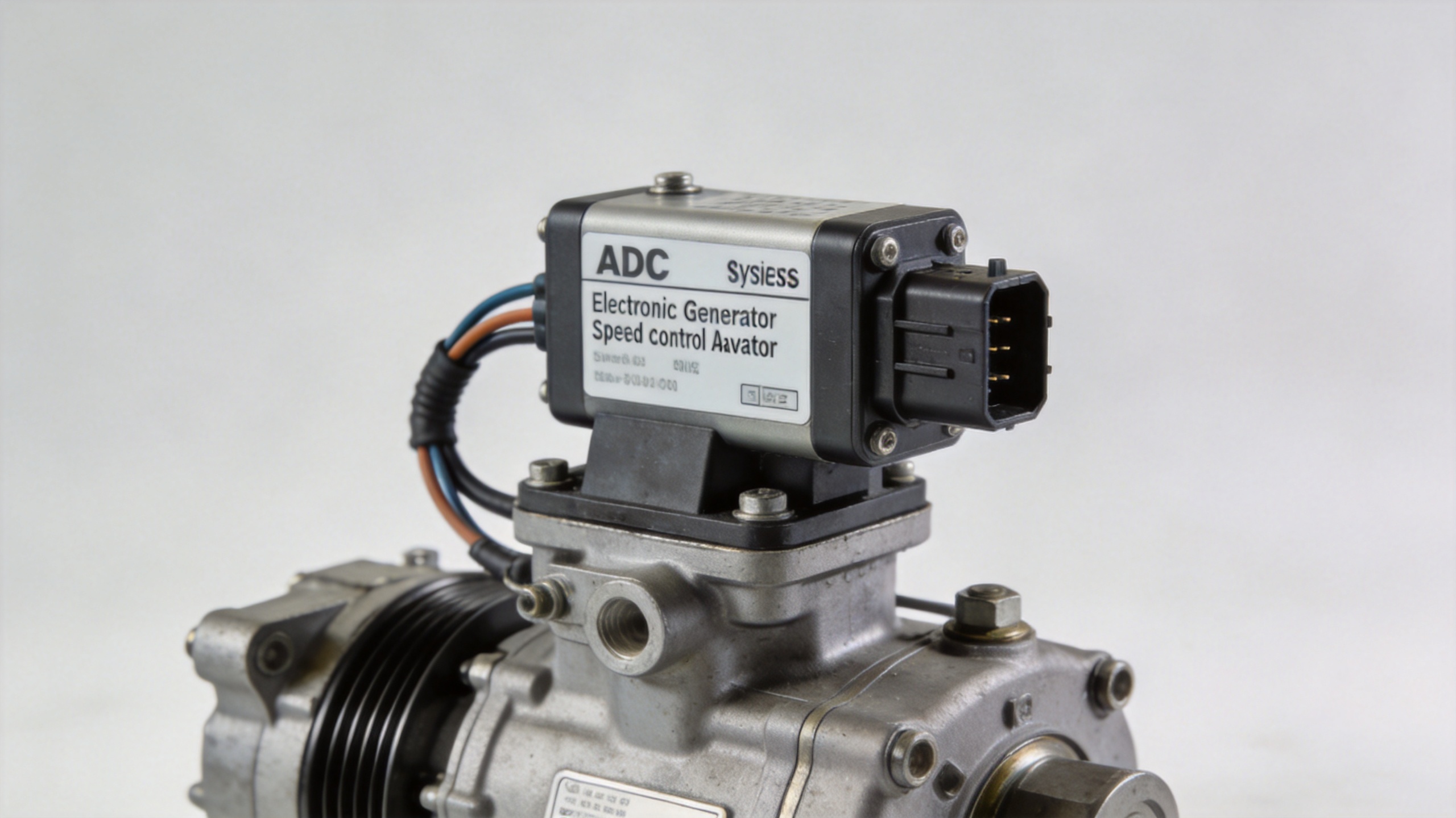
Electronic governors replace this sensing chain with a magnetic pickup (MPU) that reads toothed-wheel pulses, feeding a control board that drives a generator speed control actuator to reposition the fuel rack. This architecture delivers faster transient response, tighter frequency regulation, and remotely adjustable gain settings that a purely mechanical system cannot match.
For industrial diesel engines, the POPULACE External Actuator range — including the ADC120, ADC175, and ADC225 models in 12V and 24V — covers a broad spectrum of engine displacements and fuel rack force requirements. These units serve as direct-fit generator speed control actuators for both retrofit upgrades and new installations where the control board already handles speed sensing and output signal generation.
Isochronous Control: Constant-Speed Operation
Isochronous control holds engine speed at exactly the programmed set point regardless of load magnitude. Load a generator from 0% to 100% of rated capacity, and the output frequency stays at 50.0 Hz (or 60.0 Hz). This makes isochronous genset governor types the correct specification for:
- Single-unit standby or prime power applications supplying frequency-sensitive loads such as variable frequency drives, medical equipment, or precision instrumentation
- Mobile power stations that operate in isolation from the utility grid
- Island-mode parallel systems where one machine is designated as the master frequency reference
The trade-off is that a purely isochronous governor has a flat regulation curve — it does not naturally distribute load between parallel units. Connect two isochronous generators to the same bus without an external load-sharing controller and one machine will absorb all the load while the other hunts. Droop control solves this.
Droop Control: Speed Regulation and Load Distribution
A droop governor intentionally permits engine speed to decrease as load increases, with the reduction expressed as a percentage of rated speed. A standard droop setting of 3–5% means that at full load the engine runs 3–5% slower than at no load. At 5% droop on a 50 Hz machine, no-load speed corresponds to approximately 52.5 Hz and full-load speed to 50.0 Hz.
The sloping regulation curve enables the generator load sharing principle to function automatically. When two generators with identical droop settings are paralleled, any increase in bus load causes both engines to slow proportionally. Because their speed-versus-load curves overlap on the same frequency axis, both units automatically absorb additional load in proportion to their rated capacity — without external arbitration.
Common parallel configurations and their behavior:
- Both units on matched droop (e.g., 5%): Load sharing is stable and automatic; no external load-sharing controller required.
- One unit isochronous, one on droop: The isochronous machine acts as the frequency master; the droop unit adjusts output to match the frequency reference. Reactive load must still be handled by AVR droop independently.
- Both units on isochronous without external control: Parallel instability results; this configuration is unsuitable for production use.
The shift most experienced operators make is recognizing that genset governor types are not interchangeable — the choice between droop and isochronous depends on whether the application is single-unit island, multi-unit island, or grid-parallel, not on brand preference.
Generator Reactive Power Control in Parallel Systems
Speed droop governs active power (kW) sharing between parallel generators. Generator reactive power control — regulation of reactive output (kVAR) — is a separate function managed by the AVR through reactive droop or cross-current compensation.
Without reactive droop, paralleled generators with balanced kW loading can still circulate reactive current between machines — causing one unit to over-excite while the other under-excites. Correct generator reactive power control mirrors the active load-sharing principle: each AVR's output voltage droops slightly as reactive load increases, creating a stable kVAR-sharing characteristic analogous to speed droop.
When specifying governor units for parallel operation, confirm the control system supports both active load sharing via governor droop and reactive power sharing via AVR reactive droop. Addressing only one side leaves the parallel system partially uncontrolled.
Comparing Electronic Governor Options: S6700H vs ESD5500E
Among the electronic genset governor types commonly deployed in the mid-range industrial segment, the S6700H and ESD5500E controllers represent two well-established platforms:
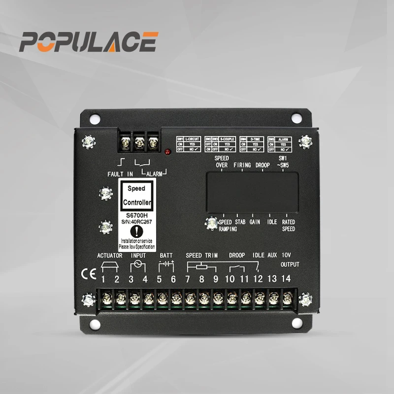
| Specification | S6700H | ESD5500E |
|---|---|---|
| Control approach | Electronic speed controller | Electronic speed governor |
| Droop / isochronous | Adjustable via droop potentiometer | Adjustable droop setting |
| Primary application | Industrial diesel gensets, prime power | Diesel gensets, broad compatibility |
| Speed sensing | Magnetic pickup (MPU) | Magnetic pickup (MPU) |
| Supply voltage | 12V / 24V DC | 12V / 24V DC |
The S6700H Governor Speed Controller is well suited for industrial prime power gensets where stable droop settings and calibrated gain adjustments are critical — particularly in applications requiring parallel operation with adjustable load sharing behavior. The ESD5500E Speed Governor is a widely deployed unit with broad engine compatibility, making it a practical choice for replacement procurement where panel wiring and actuator interface are already fixed.
If your priority is parallel stability and calibration flexibility, the S6700H's adjustable gain and stability settings are the most relevant factor to evaluate. If the use case is single-unit standby with an existing actuator harness and space-constrained panel, the ESD5500E's footprint and pin compatibility are likely the deciding factors.
Governor Calibration and Adjustment Procedure
Regardless of genset governor type selected, calibration follows a consistent sequence:
- No-load speed setting: With the generator unloaded, adjust the speed trim potentiometer until the frequency meter reads the target value (50.0 Hz or 60.0 Hz exactly). Record the trim position.
- Stability verification: Run at no load for 5 minutes. If frequency hunts, reduce governor gain slightly and recheck. Do not advance gain past the point where hunting begins.
- Stepped load application: Apply 25%, 50%, and 100% of rated load incrementally. Note the frequency at each step to establish the actual droop curve.
- Droop calibration: For parallel operation, adjust the droop potentiometer until the measured frequency drop from no load to full load equals the target percentage (typically 3–5%). For isochronous single-unit operation, reduce droop to minimum.
- Parallel close and sharing check: Verify both units are at near-identical frequency before closing the parallel breaker. After closing, check load sharing on the kW meters; adjust droop trim on the heavier-loaded unit if sharing is uneven.
- Settings documentation: Record all potentiometer positions. Governor pot settings are not visible externally and are easily lost after vibration or maintenance.
The most common calibration error is setting droop on one parallel unit without verifying the matched setting on the second. Both machines must share the same droop characteristic for the generator load sharing principle to hold across the full load range.
Summary: Matching Governor Type to Application
Selecting among genset governor types reduces to three operational questions:
- Single unit or parallel? Isochronous for single-unit island applications; droop (or isochronous with a load-sharing controller) for multi-unit parallel systems.
- Grid-connected or isolated? Droop is required for grid-parallel operation; isochronous without synchronizing controls will conflict with the grid frequency reference.
- Load characteristics? Frequency-sensitive loads favor tight isochronous regulation; motor-dominated or variable loads benefit from the damping effect of adjustable droop.
Getting genset governor types right does not guarantee an immediate visible fault on commissioning — symptoms may emerge later as gradual load imbalance, frequency instability, or reactive current circulation between parallel units. Matching the governor control mode to the operational scenario is the foundational step in a stable generating system.






