
 EN
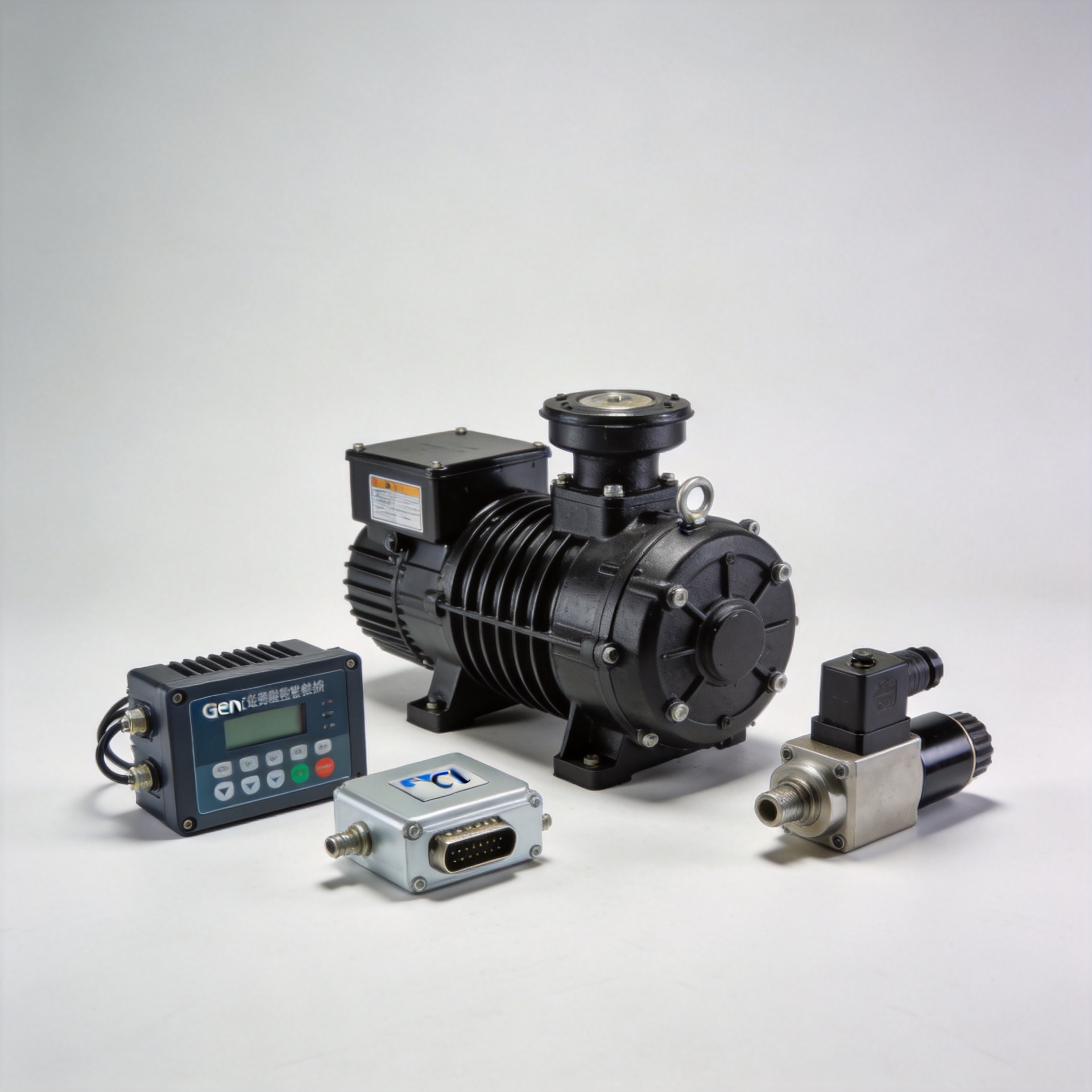
Genset Governor Control System: Overview and Specs
Working with generator parts suppliers across Asia and North America, one pattern surfaces often: procurement teams can spec the alternator and control panel with relative confidence, but the genset governor control system decision tends to stall. It involves more moving parts — literally and figuratively. The governor is not just a component — it is the system that keeps a diesel engine running at the correct speed under changing load conditions, and if it is mismatched or misconfigured, frequency instability and load-shedding follow.
This overview covers how a genset governor control system works, the difference between mechanical and electronic designs, key operating modes, critical specification parameters, and what to check during calibration. If you are evaluating replacement governors or sourcing for a fleet, these are the details that actually matter.
How a Genset Governor Control System Works
A genset governor control system operates on a closed-loop feedback principle. The system continuously measures engine speed — through a magnetic pickup or other speed governor sensor — and compares it against a set-point speed (typically 1500 RPM for 50 Hz or 1800 RPM for 60 Hz output). When actual speed deviates from the target, the governor sends a corrective signal to the fuel actuator, adjusting fuel delivery to bring speed back in line.
The three core elements of any modern electronic genset governor control system are:
- Governor control unit (ECU): Processes the speed signal, applies PID control logic, and outputs a command signal to the actuator.
- Speed governor sensor: A magnetic pickup (MPU) mounted near the flywheel ring gear, generating a frequency signal proportional to engine RPM. Signal accuracy has a direct bearing on how the governor responds to speed changes.
- Actuator: An electromechanical device that physically adjusts the fuel rack or throttle lever based on commands from the governor ECU.
This three-component architecture is what differentiates a modern electronic genset governor control system from purely mechanical designs. The speed governor sensor feeds real-time data into the control unit, which responds in milliseconds rather than relying on the slower centrifugal force response of a mechanical governor.
Mechanical vs. Electronic Governor Types
Mechanical governors come in several forms. The centrifugal flyweight design has been in service for decades and remains common in smaller gensets. A viscous speed governor uses fluid viscosity drag to smooth speed variation — useful in applications where gradual, well-damped response is preferred over fast correction. Both mechanical types share the same fundamental limitation: response time is tied to physical motion and cannot be tuned without mechanical disassembly.
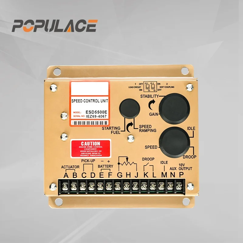
Electronic governors, by contrast, are software-configurable. Units like the ESD5500E apply PID (proportional-integral-derivative) control logic, with gain, stability, and droop parameters adjustable via potentiometers or digital interfaces. For industrial gensets and mobile power stations where load transients are frequent, electronic governors tend to deliver better speed regulation and faster load recovery than mechanical equivalents.
From a cost of speed governor perspective, electronic units like the ESD5500E sit in the mid-tier range — considerably more capable than basic mechanical governors, and significantly less expensive than premium digital controllers such as a Kohler electronic governor module or Woodward unit. For most industrial genset applications, mid-tier electronic governors represent the strongest cost-to-performance balance.
Isochronous vs. Droop Mode: Operating Mode Selection
Operating mode is one of the most consequential genset governor control system settings — and one of the most commonly misconfigured in the field.
Isochronous mode maintains constant engine speed regardless of load. The governor continuously corrects to keep frequency exactly at the set-point. This is the right mode for a single generator running independently: you want stable frequency across the full load range without intentional droop.
Droop mode allows engine speed — and therefore output frequency — to decrease proportionally as load increases. A typical droop setting of 3–5% means that at full load, frequency drops 3–5% below no-load frequency. This intentional droop is essential during parallel operation. When two or more generators share a bus, isochronous control on all units creates load hunting — each governor tries to correct speed adjustments made by the other, causing instability. With droop enabled, load distributes naturally based on each unit's speed characteristic.
Practical rule: single genset operation uses isochronous mode; parallel genset operation requires droop mode on all units (or one isochronous master with the others in droop, depending on the synchronizing panel design).
Key Specifications to Review Before Sourcing
Before selecting or sourcing a genset governor control system, verify these parameters against your application:
| Parameter | Typical Range | Notes |
|---|---|---|
| Supply voltage | 12V DC or 24V DC | Must match genset battery system voltage |
| MPU signal input | 0.5–70V AC (typical) | Confirm compatibility with your flywheel ring gear tooth count |
| Speed range | 500–3600 RPM | Should cover your engine's full operational RPM window |
| Droop adjustment | 0–10% | Set to 3–5% for standard parallel operation |
| Actuator output current | Up to 4A continuous | Must match actuator coil resistance and travel specs |
| Operating temperature | -40°C to +70°C | Verify for mobile and outdoor applications |
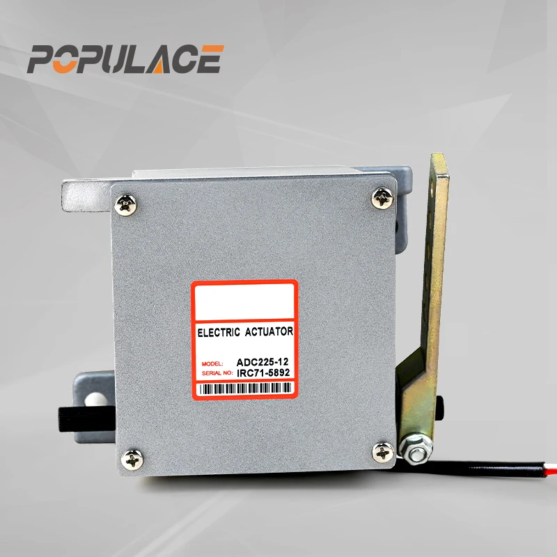
Actuator compatibility is worth thinking through carefully. A governor ECU outputs a current command signal, but the actuator converts that command into mechanical fuel rack movement. If the actuator's coil resistance or travel range does not match the governor's output spec, the control loop will not tune correctly — one of the most common and avoidable procurement pitfalls in the genset governor control system category.
Governor Adjustment and Calibration: Basic Steps
Most electronic genset governor control systems provide at least three adjustable parameters: gain (or sensitivity), stability (or damping), and droop.
- Set initial positions: Before startup, set gain to mid-position, stability to mid-position, and droop to zero for initial single-genset commissioning.
- Start under no load: Run the engine at no-load and verify steady-state speed at rated RPM. If speed hunting (oscillation) is present, reduce gain or increase stability.
- Apply load steps: Apply load in increments (25%, 50%, 75%, 100% rated load). Observe recovery time and overshoot. Increase gain if recovery is too slow; reduce gain if overshoot is excessive.
- Adjust stability: Stability (damping) affects how quickly oscillations are suppressed. Too little damping causes persistent speed hunting; too much causes sluggish response.
- Set droop (if parallel operation): Once single-genset performance is stable, set droop to the required percentage and verify load sharing during parallel commissioning.
Document final parameter settings for each governor unit on site. This becomes essential when replacing a failed unit — restoring known-good settings immediately gets a replacement unit close to correct operation without full recommissioning from scratch.
Sourcing a Genset Governor Control System
Populace Electronic Co., Ltd. manufactures and supplies electronic genset governor control systems designed for diesel engine applications across industrial and mobile generator markets. The ESD5500E Speed Governor Generator Speed Control Unit is a widely compatible 12V/24V electronic governor suitable for Cummins, Perkins, Deutz, Volvo, and other common genset engines. It supports adjustable gain, stability, and droop, and is designed as a direct replacement for original electronic governor systems.
For applications requiring different control characteristics, the S6700H Governor Speed Controller provides an alternative control profile with similar voltage and MPU signal compatibility.
Actuator selection depends on the fuel system design. The ADC120, ADC175, and ADC225 external actuators cover a range of torque and stroke requirements, with 12V and 24V variants available to match the governor control unit supply voltage.
Wholesale and distributor inquiries are handled through the Populace B2B channel at populaces.en.alibaba.com, with support for specification verification and volume orders for distribution partners in Asia, Europe, and North America.






