
 EN
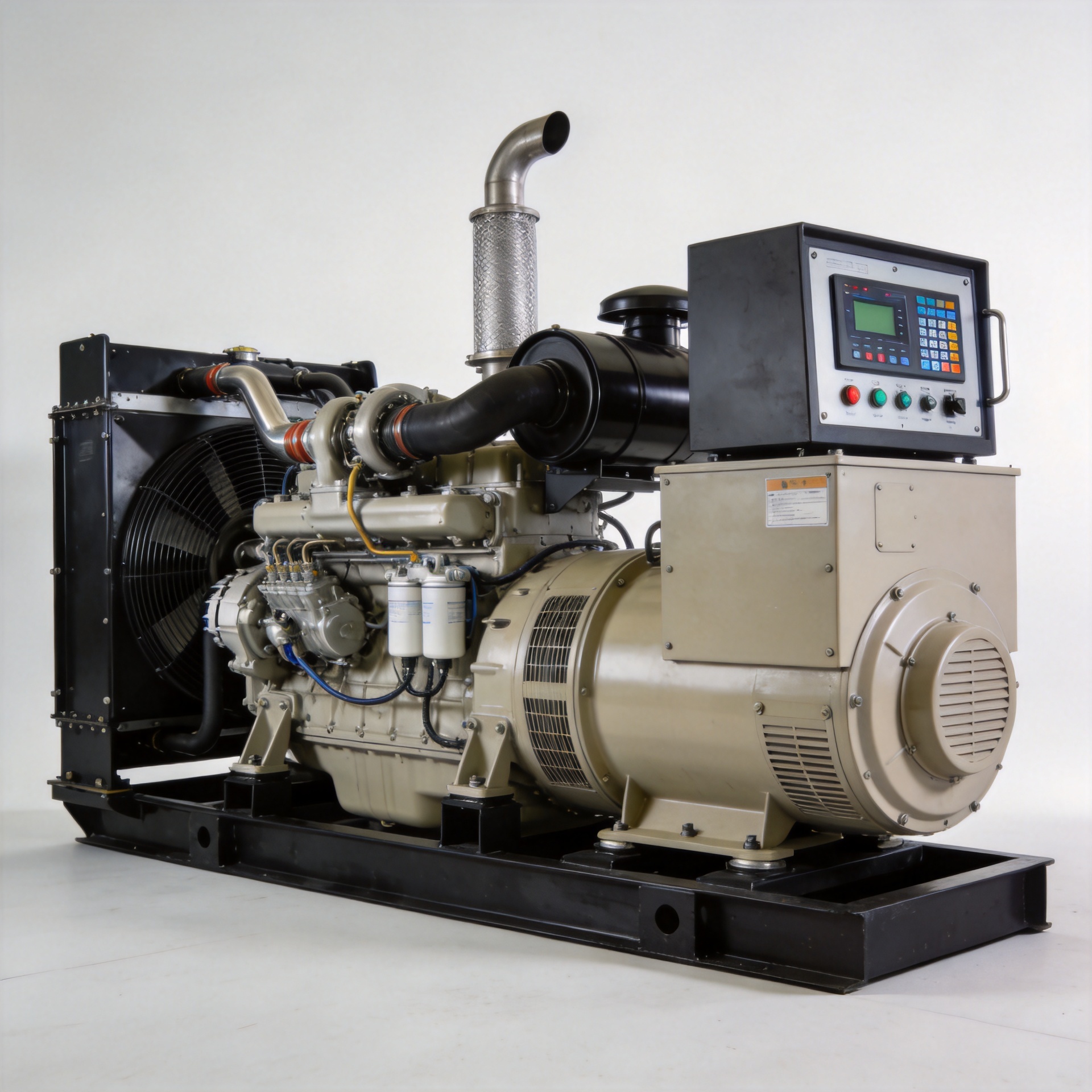
Genset Electronic Governor: Benefits and Applications
As a technical consultant who has spent years working with generator control components, I have seen firsthand how the governor choice affects a genset's reliability in the field. A genset electronic governor is not just a specification item on a parts list — it is the component that determines whether your generator maintains stable output under changing loads or fluctuates in ways that damage connected equipment. This article covers how electronic governors work, how they compare to mechanical alternatives, and which applications benefit most from the precision they offer.
What Is a Genset Electronic Governor?
A governor regulates the speed of a diesel engine by controlling fuel delivery in response to load changes. When a load is applied to a generator, the engine tends to slow down; the governor detects this and increases fuel injection to restore the target RPM. When load drops, the governor reduces fuel input to prevent over-speed.
A genset electronic governor performs this function using electronic sensors, a processing unit, and an electrically-driven actuator — rather than the flyweights, springs, and mechanical linkages used in older designs. The result is faster response times and more precise speed control across a wider load range.
Electronic vs Mechanical Governors: What Changes
Mechanical governors rely on centrifugal force: flyweights attached to the engine crankshaft move outward as RPM increases, mechanically adjusting the fuel rack to reduce injection. The system is self-contained and reasonably robust, but response time is limited by the physics of mechanical movement, and calibration is affected by wear over time.
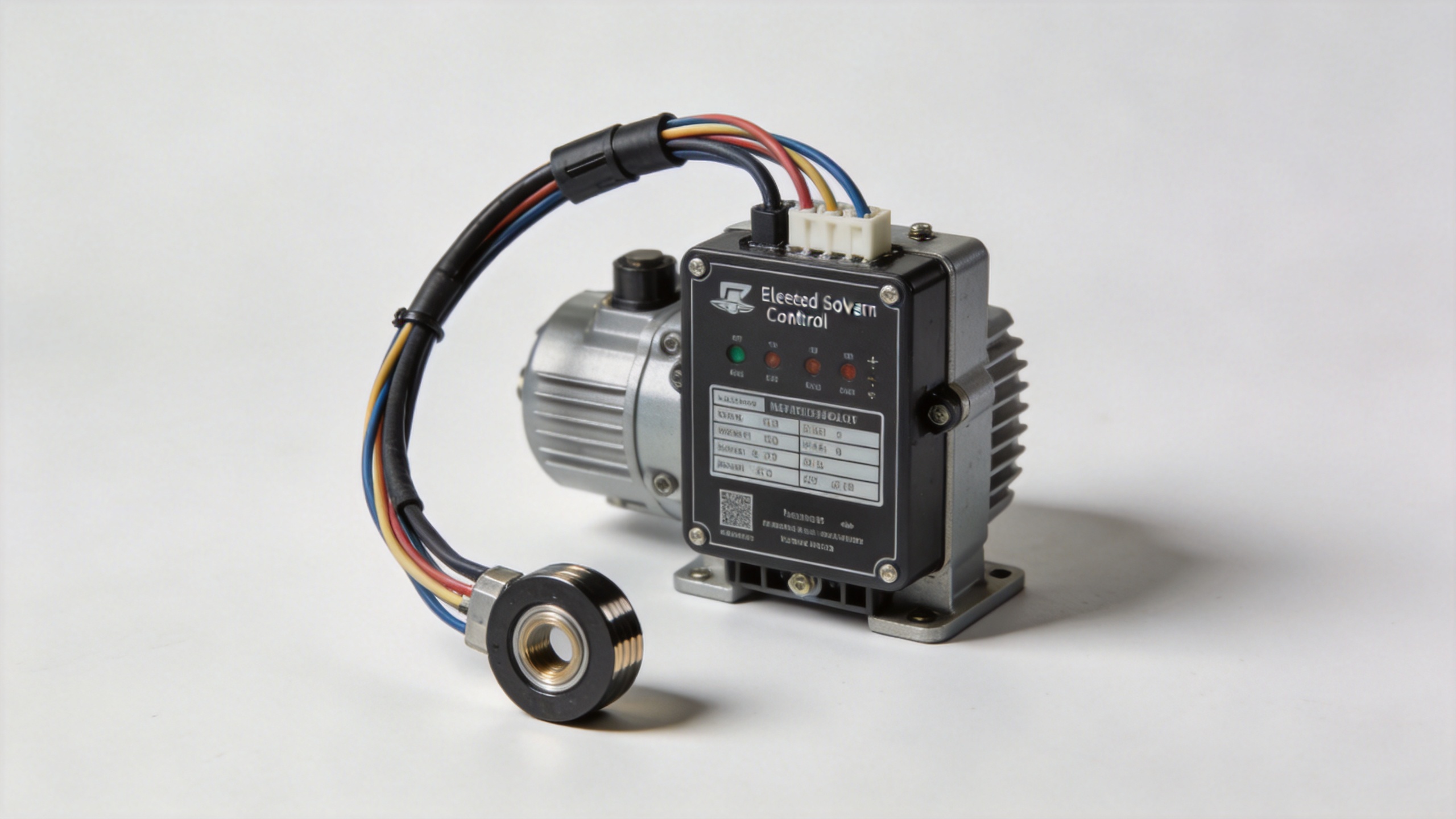
Electronic governors replace that mechanical sensing loop with a magnetic pickup sensor that detects tooth frequency from the flywheel ring gear, feeds that signal to an electronic control unit, and drives an electric actuator to adjust fuel delivery. The speed sensing is continuous and the response is near-instantaneous compared to mechanical alternatives.
Most buyers who have worked through this choice eventually recognize that it is not simply about replacing a worn part. The real question is whether the engine's control loop needs to meet tighter stability requirements than a mechanical design can deliver. If your application runs at a stable, predictable load, a properly maintained mechanical governor may remain adequate. If load swings frequently — particularly with motor loads cycling on — the faster closed-loop response of a genset electronic governor is often what prevents visible frequency and voltage instability.
Industrial Genset vs Mobile Power Station Applications
Governor requirements look quite different depending on how and where a genset is deployed.
For a stationary industrial genset — powering a facility, data center backup, or utility substation support — the priority is tight frequency regulation under sudden load steps. Loads at industrial sites can include large HVAC systems, motor drives, and sensitive instrumentation. A genset electronic governor in this environment needs fast transient response and stable steady-state regulation.
For a mobile or portable genset — such as a vehicle-mounted power unit or a rental set deployed at construction sites — durability under vibration, temperature variation, and irregular maintenance schedules becomes more important. Many mobile operators also work with mixed equipment: a technician servicing kipor generator parts, powerhorse generator parts, or honda generator accessories may encounter different engine governor architectures depending on what equipment is in the field. Electronic governors that use a standard actuator interface and clear wiring documentation reduce that service complexity considerably.
Isochronous and Droop Mode: Choosing the Right Operating Mode
One of the more consequential configuration decisions for a genset electronic governor is the choice between isochronous and droop operating modes.
In isochronous mode, the governor maintains a constant target speed — and therefore constant output frequency — regardless of load level. This is the standard setting for a standalone genset: the governor corrects continuously to keep frequency at exactly the rated setpoint. Most single-unit standby and prime power installations run isochronous.
Droop mode works differently: the governor allows engine speed to decrease as electrical load increases, typically by 3–5% from no-load to full-load. At a nominal 1500 RPM, that means the engine might run at approximately 1545–1575 RPM at no load, settling to 1500 RPM at full load. This intentional droop is what enables stable load sharing when two or more generators operate in parallel: each set naturally carries a proportional share of the total load without competing for dominance on the common bus frequency.
Selecting the wrong mode — or misconfiguring droop percentage — is one of the most common errors in field installations. For a 12kw briggs and stratton generator or similar mid-range genset added to a small parallel system, setting the droop to match the other unit on the bus is essential before closing the paralleling breaker. The ESD5500E Speed Governor Generator Speed Control Unit supports both isochronous and droop modes with adjustable parameters, making it practical for technicians configuring single-unit or parallel operation without switching hardware.
Key Benefits of a Genset Electronic Governor
- Faster transient response: Electronic sensing and actuation reduce the lag between a load step and the fuel correction, minimizing frequency excursion during transient events.
- Adjustable parameters: Gain, stability, and speed droop can be tuned electronically — without disassembling governor linkages — to match the engine characteristics and load profile.
- Compatibility with parallel operation: Precise droop control and load-sharing support make electronic governors the standard choice for gensets operating in bus-connected configurations.
- Reduced mechanical wear: Removing the mechanical sensing mechanism eliminates the wear and calibration drift associated with flyweight springs over long service intervals.
- Retrofit potential: Many electronic governor systems can replace existing mechanical governors on older engines without major engine modifications, using the existing actuator mounting or a compatible replacement.
Electronic Governor Products from KYGEN Power
The S6700H Governor Speed Controller Diesel Engine Generator Speed Control Unit is designed for diesel engine generator speed regulation in both standalone and parallel configurations. The control unit interfaces with a standard magnetic pickup for speed sensing and connects to an electric actuator on the engine fuel system, providing a complete closed-loop control solution.
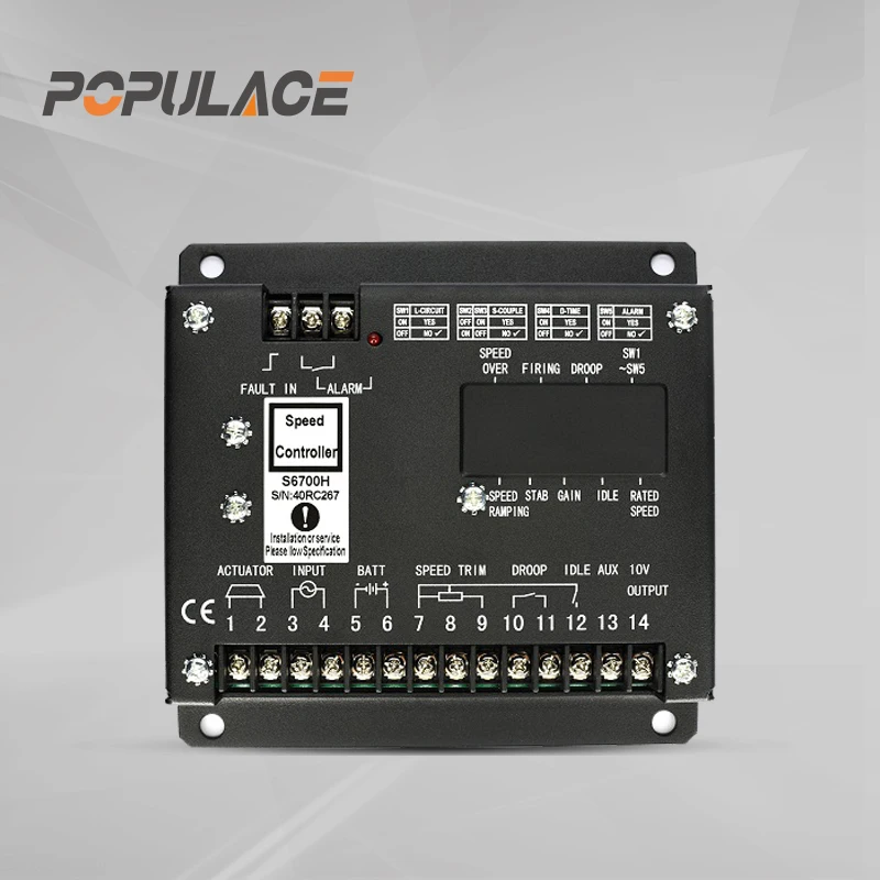
For applications that require an external actuator — particularly engines using ADC-series electric actuators — the POPULACE Diesel Generator Engine Parts External Actuator (ADC120, ADC175, ADC225) is available in 12V and 24V configurations. Confirming actuator model and supply voltage before ordering is the single most important step to avoid compatibility issues — a point reinforced by the technical documentation provided for each actuator variant.
Calibration Reference: What to Verify Before Commissioning
When installing or replacing a genset electronic governor, the following parameters typically need verification before the unit goes into service:
- Rated speed setpoint: Match the engine's nominal speed — 1500 RPM for 50 Hz systems, 1800 RPM for 60 Hz systems — or confirm the target from the engine data plate.
- Gain and stability settings: Set initial gain conservatively and increase gradually while observing speed stability under no-load and step-load conditions. Hunting (oscillation) indicates too much gain; sluggish recovery after a load step indicates too little.
- Droop setting: If the unit operates in parallel, configure droop percentage to match the other generators on the bus. A typical range is 2–5%.
- Magnetic pickup air gap: Confirm the pickup gap meets the specification for the specific flywheel tooth height — too wide a gap produces a weak signal; too narrow risks contact damage under thermal expansion.
- Actuator travel and direction: Verify that increasing governor output drives the fuel rack in the fuel-increase direction, and that the actuator reaches both the full-fuel and fuel-cutoff positions within its travel range.
Having the governor datasheet and engine wiring diagram on hand during commissioning is not a formality — it is the difference between a clean installation and a diagnostic session that stretches into the next shift.
Summary
A genset electronic governor offers measurable advantages over mechanical designs in applications where load stability, parallel operation, or long-term calibration consistency are priorities. Understanding the difference between isochronous and droop mode, matching the governor and actuator to the specific engine, and following a structured commissioning process are the steps that determine whether the installation performs as expected. For technical procurement teams evaluating options, reviewing the supplier's parameter documentation and confirming actuator compatibility are more reliable indicators of suitability than brand recognition alone.






