
 EN
Generator Speed Governor: How to Select and Maintain
The speed governor is one of the most consequential components in a diesel generator set. It controls engine RPM by regulating fuel delivery in response to load changes, keeping output frequency stable whether the generator is running alone or in parallel with other units. Get this component wrong and you end up with unstable frequency, hunting, or load-sharing failures. Get it right and the rest of the system performs as expected.
This guide covers the practical selection and maintenance decisions buyers and technicians encounter most often: the mechanical vs. electronic divide, application-specific requirements for industrial generators and mobile power stations, isochronous vs. droop operating modes, and the calibration steps that keep a governor performing reliably over time.
How a Speed Governor Controls Engine RPM
A speed governor device works on a feedback principle. It measures actual engine speed, typically via a magnetic pickup reading the flywheel ring gear, and adjusts the fuel rack position on the injection pump to correct any deviation from the set point. The response speed and accuracy of that correction loop is what differentiates governor types and determines which applications each is suited for.
The basic control loop applies to all governor types, but the mechanism and precision differ significantly between a mechanical engine governor and a modern electronic unit. This difference becomes critical when load swings are frequent, when paralleling is involved, or when the application demands tight frequency tolerance.
Mechanical Engine Governor vs. Electronic Speed Governor
The mechanical engine governor has been the standard on smaller diesel gensets for decades. It uses centrifugal flyweights rotating on the engine shaft: as speed increases, the flyweights extend outward, and that mechanical movement closes the fuel rack. The system requires no external power and is straightforward to service in the field.
The practical limitation is accuracy. Mechanical governors typically hold speed within ±2–3% across load changes, which translates to a frequency swing that many sensitive loads cannot tolerate. For standalone operation on utility-grade equipment or general industrial loads, that tolerance is often acceptable. For data centers, medical facilities, or any application requiring output within ±1% frequency, it is not.
Electronic speed governors operate through an electronic control module connected to an actuator, either a linear or rotary type, that moves the fuel rack. The control module compares the magnetic pickup signal to a programmed set point and sends corrective output in milliseconds. Speed accuracy improves to ±0.25–0.5%, and the response to sudden load acceptance is noticeably faster.
If your application runs at a stable load profile on a standalone unit, a well-maintained mechanical governor will often hold. If the load swings frequently, or if the generator must respond to step-load additions without frequency dip, the electronic type is the appropriate choice.
Application Scenarios: Industrial Generators and Mobile Power Stations
Industrial gensets installed in fixed facilities, such as factories, data centers, and hospitals, typically operate in one of two configurations: single-unit standby or multi-unit parallel. The governor selection and configuration differ for each.
In a single-unit standby installation, the generator runs alone under varying load. An isochronous-configured electronic governor maintains constant speed regardless of load change. This is the preferred setup when the load profile is unpredictable and frequency stability directly affects process equipment.
Mobile power stations, including trailer-mounted gensets used in construction, events, and emergency deployment, often prioritize reliability and serviceability over precision. A mechanical governor or a basic electronic speed governor device is common in this segment. The typical requirement is stable no-load to full-load operation, with less emphasis on sub-1% frequency precision.
Buyers sourcing for mobile applications often ask about compatibility with deep sea electronic control systems, including platforms like the deep sea electronics 4520. In these setups, the AMF/ATS controller manages start, stop, and protection functions, while the speed governor handles RPM regulation separately. Confirming that the governor's signal interface and actuator type match the controller wiring before purchase eliminates the most common compatibility problems.
Isochronous vs. Droop Mode: Single Unit and Parallel Operation
This is the configuration decision that causes the most errors in field installations. The operating mode must match the generator's role in the system.
Isochronous mode keeps engine speed at a fixed set point, typically 1500 RPM for 50 Hz applications or 1800 RPM for 60 Hz, regardless of load. The governor corrects any deviation immediately. This mode is correct for a single unit supplying an isolated load, and also for paralleling generators in island mode when an active load-sharing controller is managing kW distribution between units.
Droop mode intentionally allows engine speed to decrease as load increases. The typical droop setting is 4–5%, meaning the engine drops from rated speed at no load to approximately 95–96% of rated speed at full load. This slight speed difference between units causes load to distribute naturally between paralleled generators without active communication. Droop mode is required when paralleling to the utility grid and when load-sharing controllers are not installed.
Running two generators in parallel with both governors set to isochronous mode, without a functioning load-sharing controller, will result in one unit taking all the load while the other motorizes. This is a common cause of trip events in multi-generator installations. Verify the operating mode before commissioning, and confirm mode compatibility with any deep sea electronic or other controller platform in the system.
Governor Calibration and Maintenance
A governor that is not periodically calibrated will drift from its original settings. The calibration process varies between mechanical and electronic units, but both follow the same verification sequence.
- Record baseline performance. Log no-load speed and full-load speed before making adjustments. This establishes the current operating condition.
- Check and adjust speed set point. On mechanical governors, this is a physical adjustment screw. On electronic units, use the gain and speed-trimmer potentiometers or the software interface if the module supports it.
- Verify stability. Apply a step load equal to 25–50% of rated capacity. The governor should recover to within ±1% of set speed within 5–10 seconds. Oscillation or slow recovery indicates a gain adjustment is needed.
- Check actuator linkage. On electronic governor systems, inspect the actuator rod, clevis pins, and fuel rack connection for wear, corrosion, or binding. An external actuator that moves sluggishly will slow the governor response regardless of electronic settings.
- Inspect wiring and pickup signal. A magnetic pickup gap that has drifted outside specification produces a weak signal that causes erratic speed sensing. The gap is typically set to 0.5–1.5 mm; verify against the manufacturer spec.
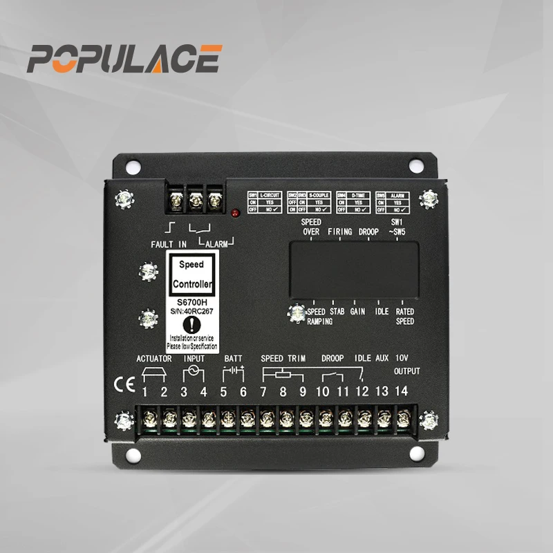
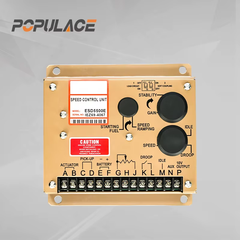
For buyers sourcing replacement governors or actuators, the S6700H Governor Speed Controller Diesel Engine Generator Speed Control Unit is a compact electronic governor designed for diesel generator applications, covering a broad range of engine sizes. The ESD5500E Speed Governor Generator Speed Control Unit is a widely referenced electronic governor module compatible with a range of actuator types. Where the mechanical linkage between governor and fuel rack requires replacement, the ADC120/ADC175/ADC225 External Actuator series covers 12V and 24V supply configurations across multiple torque ratings.
Technical pre-sales support is available for specification confirmation before order placement, which reduces the risk of receiving a component that does not match the existing fuel rack or actuator interface. For wholesale and B2B inquiries, reach the team at [email protected] or through the product pages at kygenpower.com.
Summary: Selection Checklist
- Single unit, stable load, no paralleling: mechanical or basic electronic governor is sufficient.
- Single unit, variable load, sensitive equipment: electronic governor in isochronous mode.
- Parallel operation (island mode, load-sharing controller present): electronic governor, isochronous mode.
- Parallel operation (grid-parallel or no load-sharing controller): electronic governor, droop mode at 4–5%.
- Compatibility check: confirm actuator type (linear vs. rotary), supply voltage (12V or 24V), and controller signal interface before purchase.
- Calibration: perform baseline logging before any adjustment, verify step-load recovery within specification after.
The right speed governor device for any generator comes down to three factors: load profile, operating configuration, and mechanical compatibility. Matching all three before procurement eliminates the compatibility problems that account for most governor-related service calls.






