
 EN
Generator Governor: Types and How They Work
A generator governor is the speed-control system that tells a diesel engine how much fuel to deliver so the alternator stays near its intended frequency. For buyers and maintenance teams, it is not merely an engine accessory: governor behavior affects frequency stability, load acceptance, fuel-rack response, and the way multiple generator sets share load. The right choice starts with the engine, actuator, speed sensing method, and operating mode—not with a controller name alone.
What a generator governor actually controls
When electrical load rises, the engine tends to slow down. A generator governor senses that change, commands more fuel through the actuator or fuel-control linkage, and brings speed back toward the selected setpoint. When load falls, it trims fuel back. This closed loop is why a diesel engine governor is central to stable AC output: alternator frequency follows engine speed.
The usual synchronous-speed relationship is N = 120f / P, where N is rpm, f is frequency, and P is the number of poles. That means a four-pole machine is commonly set around 1500 rpm for 50 Hz or 1800 rpm for 60 Hz; a two-pole machine is commonly around 3000 rpm for 50 Hz or 3600 rpm for 60 Hz. Use the engine and alternator nameplates plus the commissioning documentation as the final authority before changing a setpoint.
Mechanical and electronic diesel engine governors
Mechanical governors
A mechanical governor uses rotating flyweights, springs, and linkage. As speed changes, centrifugal force moves the mechanism and adjusts fuel delivery. This arrangement is rugged and simple, which can suit basic engines and applications where a modest speed variation is acceptable. Its limits are usually slower response, less flexible tuning, and fewer options for remote setpoint control or load sharing.
Electronic governors
An electronic generator governor uses a speed signal—often from a magnetic pickup—together with a controller and actuator. The controller compares measured speed with the target, then corrects fuel position. This gives diesel engine governors more tuning options for gain, stability, idle, ramping, and control mode. It is often the practical route when a set must handle rapid load steps, remote control, or synchronized operation, provided the controller, pickup, actuator, and engine fuel system are compatible.
Isochronous versus droop control
These two modes are frequently confused during specification. In isochronous mode, the generator governor aims to hold its speed setpoint as load changes. For a single generator serving an isolated load, that supports tight frequency control. In droop mode, the reference intentionally falls by a controlled amount as load rises. The change is deliberate: generators operating in parallel can then share load without fighting each other for the same speed reference.
| Operating situation | Typical governor objective | What to verify |
|---|---|---|
| Single industrial generator | Stable nominal speed and frequency | Engine response, actuator travel, pickup signal, load-step behavior |
| Parallel generator sets | Predictable load sharing | Matched droop settings or an engineered isochronous load-share scheme |
| Mobile power station | Recovery after changing loads and transport vibration | Wiring retention, overspeed protection, enclosure access, field serviceability |
Do not assume that “isochronous” is automatically better. A single set may benefit from it, while a paralleled plant needs a coordinated control philosophy. The governor, synchronizer, load-share equipment, breaker logic, and protection settings must be commissioned as one system.
Industrial sets and mobile power stations need different priorities
An industrial standby or prime-power set may face known load profiles, fixed switchgear, and planned maintenance. Here, a generator governor is commonly selected for repeatable response, integration with the control panel, and stable behavior with the intended engine. A mobile unit can experience abrupt load changes, environmental exposure, cable movement, and limited service time. For that setting, connector security, installation access, and a clear calibration procedure can matter as much as fine adjustment range.
A generator canopy also changes the service conversation. The enclosure should allow technicians to inspect the speed sensor path, actuator linkage, grounds, and controller connections without creating unsafe access around hot or moving parts. A well-protected canopy is useful, but it should not turn routine governor checks into an extended disassembly job.
How to evaluate a diesel engine governor controller
- Confirm the engine and actuator interface. Match the controller to the supported actuator arrangement and available supply voltage; do not infer compatibility from a similar-looking unit.
- Check the speed-sensing path. Verify the magnetic pickup or other sensor type, target geometry, wiring route, shielding, and signal quality.
- Define the operating mode first. State whether the set is standalone, droop-paralleled, or part of an engineered isochronous load-sharing system.
- Plan commissioning access. The commissioning team should be able to observe frequency, speed, load, and actuator movement safely while changing one parameter at a time.
- Buy against documented requirements. Compare service support, traceable compatibility information, and total installed value rather than relying on unverified performance comparisons.
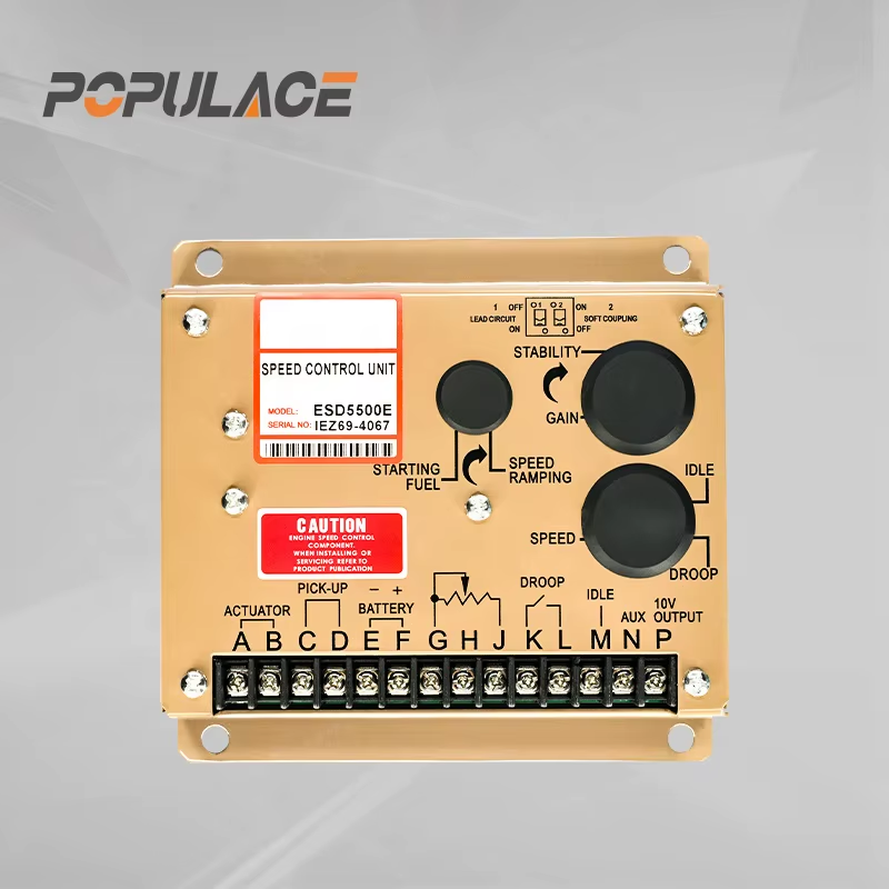
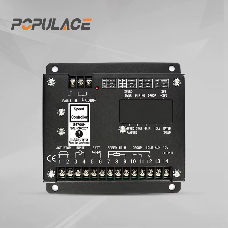
For component sourcing, the confirmed product catalog includes the S6700H Governor Speed Controller Diesel Engine Generator Speed Control Unit, the ESD5500E Speed Governor Generator Speed Control Unit Diesel Engine ESD5500E, and a POPULACE external actuator for generator speed governor applications. Treat their published documentation and the engine application requirements as the basis for final compatibility review.
Safe adjustment and calibration sequence
- Review the engine manual, alternator data, protection settings, and controller documentation. Isolate the set according to site procedures before touching wiring or linkage.
- Inspect the mechanical installation: actuator mounting, linkage freedom, return springs, sensor gap, connectors, grounds, and signs of chafing or water entry.
- With qualified personnel and suitable instruments, establish the specified no-load speed/frequency. Make small changes only, allowing the system to settle after each adjustment.
- Apply staged load steps within the set’s approved capability. Observe frequency recovery, hunting, smoke, actuator travel, and alarms; do not tune past protective limits.
- For parallel operation, coordinate droop or load-share settings across the complete plant, then document the final values and test results.
If the engine surges, overspeeds, fails to pick up load, or shows an unstable speed signal, stop the test and diagnose the installation rather than continuing to adjust. Incorrect governor tuning can create equipment and personnel hazards.
Conclusion
A generator governor keeps diesel-engine speed aligned with the electrical job the generator must do. Mechanical designs remain relevant for simple duty, while electronic diesel engine governors offer the feedback and configuration needed for demanding load response and coordinated operation. Specify the control mode first, confirm the engine-actuator-sensor combination, and commission with measured speed, frequency, and load data. That approach gives procurement teams a defensible path from controller selection to reliable field performance.






