
 EN
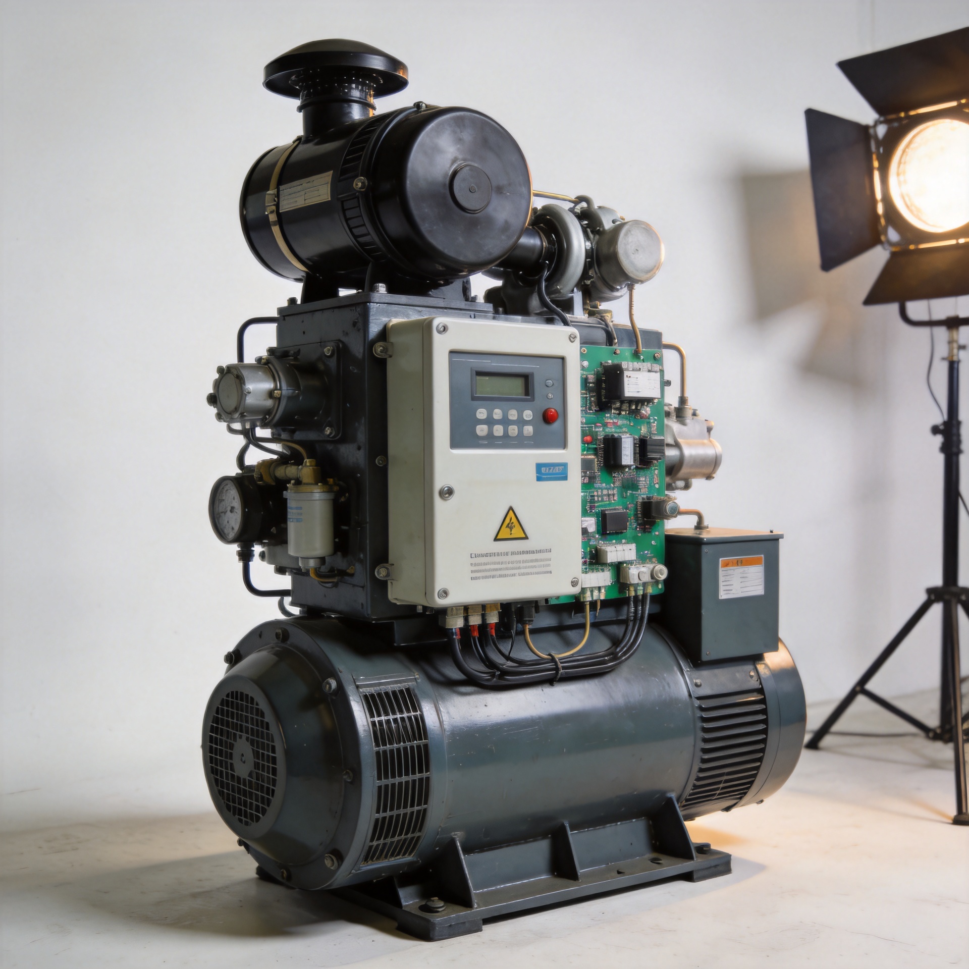
Generator Engine Speed Controller: Electronic Overview
When evaluating generator components for an industrial procurement project, the generator engine speed controller is one of the specifications that separates a stable, long-term power solution from a unit that creates operational problems under variable load. As a component-level technician with experience across diesel genset configurations, governor type and operating mode together affect real-world generator performance more than most buyers initially expect. This overview covers how electronic governors work, the difference between mechanical and electronic types, and what to verify before sourcing a replacement or upgrade.
What a Generator Engine Speed Controller Does
A generator engine speed controller — also called a governor or engine speed control system — maintains engine rotational speed within a defined target range regardless of electrical load changes. In a diesel generator, when connected load increases, the engine naturally decelerates. The governor detects this deviation and signals the fuel injection actuator to increase fuel delivery, restoring engine speed to the target setpoint. When load decreases, the reverse correction applies.
The precision of this response determines output frequency stability. For a 50Hz generator, the target engine speed is typically 1500 RPM; for 60Hz applications, the target is 1800 RPM. A generator engine speed controller that allows excessive speed deviation produces frequency fluctuations that can damage downstream equipment. This is why the control unit's regulation accuracy and response speed are the two most critical specifications when evaluating options.
Electronic vs Mechanical Governor: What Changes at the Component Level
The distinction between mechanical and electronic governor in diesel engine applications is significant for buyers who prioritize accuracy and response speed. Mechanical governors use centrifugal flyweights to respond to speed changes. They are reliable in stable-load environments and require no electronic infrastructure, but their regulation accuracy is limited and their load-response recovery is comparatively slow.
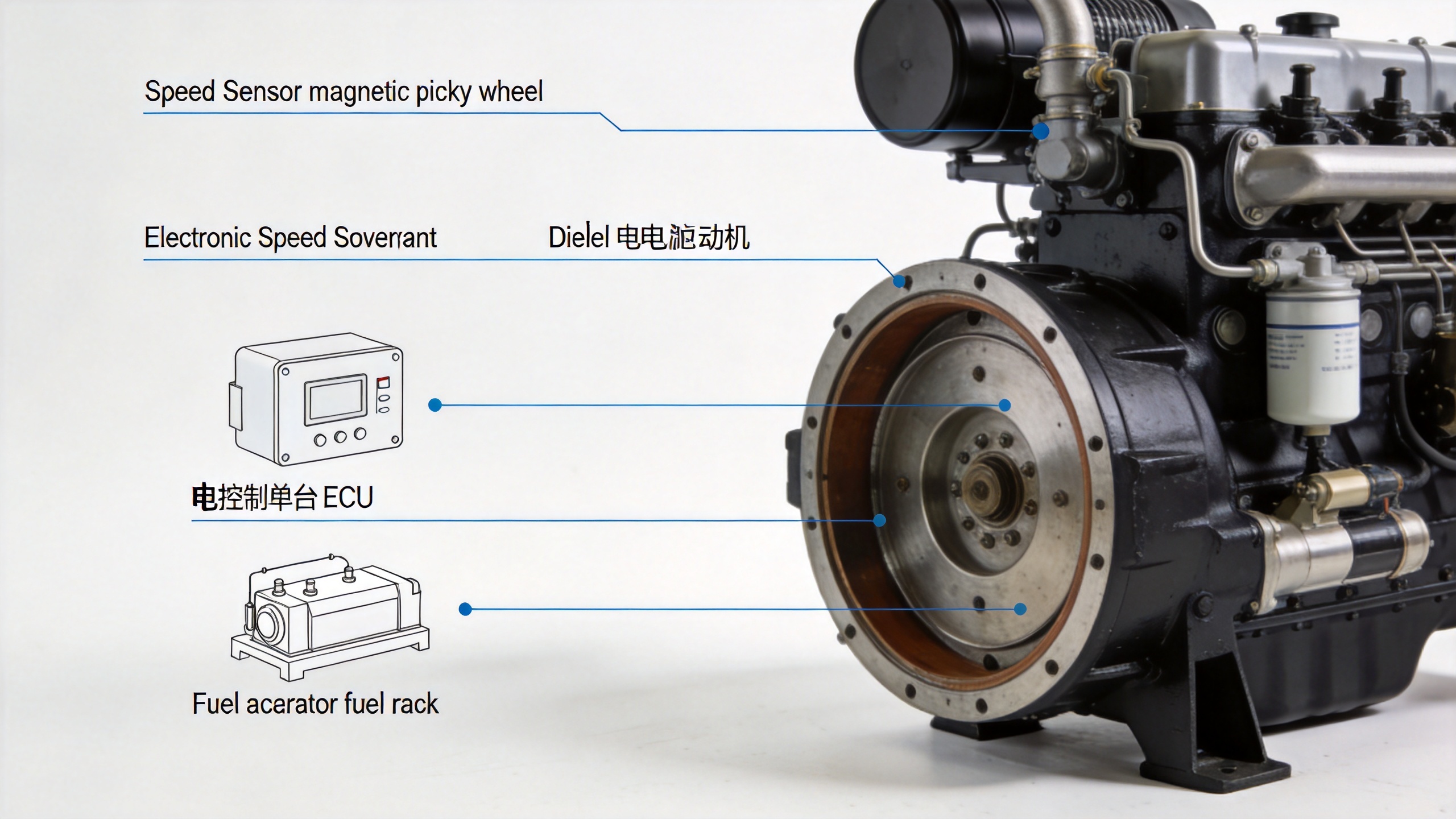
An electronic governor uses speed sensors — typically magnetic pickup sensors measuring flywheel tooth frequency — and a dedicated control unit to monitor and adjust engine speed. The response is faster and regulation accuracy is substantially higher. For buyers considering a petrol generator governor replacement or an electronic upgrade for a diesel unit, the performance improvement in dynamic load scenarios is measurable: electronic types recover from sudden load applications significantly faster than mechanical equivalents.
| Parameter | Mechanical Governor | Electronic Governor |
|---|---|---|
| Regulation Accuracy | Low | High |
| Load Response Speed | Slow | Fast |
| Installation Complexity | Low | Medium |
| Suitable for Parallel Operation | Limited | Yes |
| Adjustable via Potentiometer | No | Yes |
How an Electronic Governor in a Diesel Engine Works
The operating sequence of an electronic governor in diesel engine applications follows a closed-loop feedback process. The speed sensor monitors engine RPM and transmits a frequency signal to the electronic control unit. The control unit compares the measured speed against the internal setpoint. If a deviation is detected, the unit sends a corrective signal to the actuator, which adjusts the fuel rack position on the injection pump. This cycle repeats continuously, keeping engine speed within the defined operating band.
The actuator is a separate hardware component — typically an electro-mechanical device — that physically moves the fuel control linkage. When sourcing a complete engine speed control system, confirming compatibility between the electronic control unit and the actuator type is a required verification step. A mismatch between control unit output current range and actuator input specification is a common procurement error that results in field installation failures. The actuator torque rating must also match the mechanical resistance of the specific injection pump fuel rack.
Isochronous and Droop Control Modes
If your application runs at a stable load profile, the isochronous setting for a generator engine speed controller will hold well. If the load swings frequently (particularly with motor loads cycling on and off), understanding how droop mode changes control behavior is important before selecting a configuration.
In isochronous mode, the generator engine speed controller attempts to maintain engine speed at the exact nominal value (1500 RPM for 50Hz or 1800 RPM for 60Hz) across all load levels. This is the standard configuration for a standalone petrol generator governor or diesel generator operating independently. Output frequency remains stable regardless of load variation.
In droop mode, the governor permits a controlled speed decrease as load increases. At no load, engine speed typically runs 3–5% above nominal (approximately 1545–1575 RPM for a 50Hz unit). At full load, speed returns to the 1500 RPM target. This intentional speed differential enables load sharing when generators are run in parallel: each unit's output contribution scales proportionally with speed deviation, preventing one unit from absorbing all added load.
The practical rule: standalone generators use isochronous mode; paralleled generator sets use droop mode. Running a standalone generator in droop mode will produce frequency deviation under varying loads — not recommended for precision or sensitive-load applications.
Industrial Generator vs Mobile Power Station Speed Control Requirements
Speed control requirements differ meaningfully between fixed industrial generators and mobile power station deployments. Industrial prime power applications typically operate under predictable load profiles where long-term frequency stability and low maintenance are the priorities. Mobile or temporary power deployments face larger and more frequent load swings, often requiring a generator engine speed controller with faster response capability and broader actuator compatibility across different engine makes and models.
For mobile applications and electronic governor for small engines in generator sets, operating voltage range (commonly 10–32VDC) and input frequency range (typically 1–7.5 kHz for magnetic pickup sensors) are two specifications that must be confirmed against the specific engine's sensor output. Sourcing a controller without verifying these parameters against the engine's sensor output is among the most frequently reported compatibility issues in this product category.
Adjustment and Calibration Steps
That covers the basic configuration of a generator engine speed controller. Here is where it becomes more practical: adjusting gain, stability, and droop settings on an electronic unit requires the generator to be under controlled load during calibration.
- Set initial gain to minimum: Start with the gain potentiometer at its lowest setting to prevent over-response during initial startup.
- Start engine unloaded: Bring the engine to operating temperature before making speed adjustments.
- Adjust speed setpoint: Use the speed reference potentiometer to bring engine RPM to target (1500 or 1800 RPM as applicable).
- Increase gain gradually: Raise the gain setting until engine speed holds stable without oscillation or hunting.
- Apply load in steps: Connect loads incrementally and observe speed recovery time. If governor hunting occurs, reduce gain slightly and recheck stability.
- Set droop percentage if required: For parallel configurations, set droop to match across all units — typically 3–5% for even load distribution.
- Record final settings: Document all potentiometer positions for reference during future maintenance or replacement.
One counter-intuitive point worth noting: faster governor response is not necessarily better. For generator sets with stable resistive loads, an overly high gain setting causes instability rather than improved control. Calibrate the engine speed control system to match the actual load environment — not to maximum sensitivity.
Electronic Speed Controllers: Sourcing Options
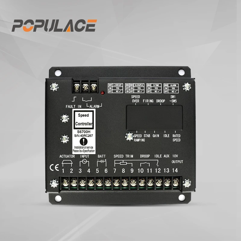
KYGEN Power supplies generator engine speed controller units compatible with a range of diesel and gas engine configurations. For diesel generator applications, two units are commonly sourced:
- The S6700H Governor Speed Controller Diesel Engine Generator Speed Control Unit supports both isochronous and droop operation, making it suitable for both standalone and parallel generator configurations. The unit is an industrial-grade option for prime power applications requiring stable frequency output.
- The ESD5500E Speed Governor Generator Speed Control Unit Diesel Engine ESD5500E is a widely sourced replacement controller with a 10–32VDC operating range and standard magnetic pickup input, suitable for both fixed and mobile generator applications across a wide range of diesel engine types.
For installations requiring a separate electro-mechanical actuator, the POPULACE External Actuator ADC120/ADC175/ADC225 (12V/24V) is available in three torque ratings to match different fuel pump mechanical resistance requirements. Confirming which actuator model matches the engine's fuel control linkage is part of the standard pre-order compatibility check for a complete engine speed control system.
Pre-Sourcing Verification Checklist
Before placing a procurement order for a generator engine speed controller, the following checklist reduces compatibility risk:
- Engine model and injection pump type (mechanical injection vs common rail affects governor interface requirements)
- Magnetic pickup sensor output frequency range
- Operating voltage: 12V or 24V
- Intended control mode: isochronous (standalone) or droop (parallel)
- Actuator torque requirement if the control unit does not include a built-in actuator
- Availability of installation documentation and wiring diagrams from the supplier
For buyers evaluating an electronic governor for small engines through to industrial-scale diesel units, the same compatibility verification logic applies — scale and engine type change the specific parameters, but the checklist structure remains consistent. A supplier with model-level specification matching support reduces the risk of receiving a technically valid but incompatible unit.






