
 EN
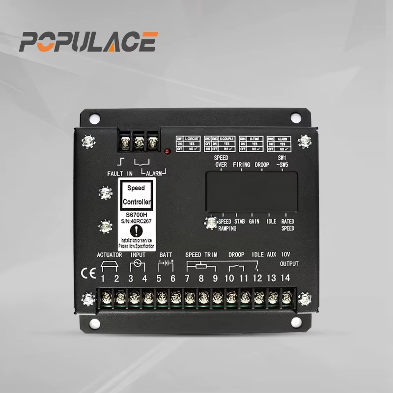
Electronic Engine Governor: How It Controls Engine Speed
When a generator suddenly takes on a heavy load, say an air conditioning system kicking in mid-cycle, the diesel engine must respond within fractions of a second to maintain stable frequency output. That response is the job of the electronic engine governor. For procurement engineers and maintenance teams working with industrial gensets, understanding how an electronic engine governor functions is often the difference between a stable, well-calibrated installation and one that perpetually chases its own setpoint.
This article covers how an electronic engine governor works, how it differs from mechanical alternatives, how mode selection affects single-unit and parallel operation, and what calibration steps matter most for field installation.
What Is an Electronic Engine Governor?
An electronic engine governor is a closed-loop control device that regulates diesel engine speed by adjusting the fuel supply in real time. For a generator set, maintaining stable engine speed — typically 1500 RPM for 50 Hz output or 1800 RPM for 60 Hz output — is what keeps output frequency stable as electrical load changes.
The governor's control loop never stops. When load increases, the engine tends to decelerate; the electronic engine governor senses this drop and increases fuel delivery. When load drops, it trims fuel back. Without this closed-loop response, a 3–4% speed deviation under moderate load swings translates directly into frequency variation that sensitive downstream equipment may not tolerate.
Mechanical vs. Electronic Governors: Key Differences
Mechanical governors use centrifugal flyweights to detect speed changes. As engine speed rises, the flyweights move outward and mechanically restrict fuel flow through a lever-and-spring assembly. The mechanism is self-contained but slow: it responds to speed changes that have already occurred, and its response time is limited by mechanical inertia.
An electronic engine governor replaces this mechanical loop with a faster, more precise one. A magnetic pickup unit (MPU) mounted near the engine flywheel generates a frequency signal proportional to engine speed. The electronic control unit reads this signal continuously, compares it against the setpoint, and drives an electromechanical actuator to adjust the injection pump rack — typically within 50–200 milliseconds.
The real-world implication is that an electronic engine governor can respond to load transients that would cause a mechanical unit to hunt or overshoot. Governor hunting — where engine speed oscillates above and below the setpoint — is among the most visible symptoms of a poorly calibrated mechanical governor. A well-tuned electronic engine governor eliminates most of this instability, though calibration still matters.
How an Electronic Engine Governor Works
The signal chain in a standard electronic engine governor system follows four stages:
- Speed Sensing: The MPU generates an AC signal whose frequency reflects engine RPM. For a 60-tooth flywheel ring gear, the MPU signal frequency at 1500 RPM is 1500 Hz — a verifiable reference point for calibration.
- Speed Comparison: The control unit compares actual frequency against the setpoint. The difference — the error signal — determines how much and in which direction the actuator must move.
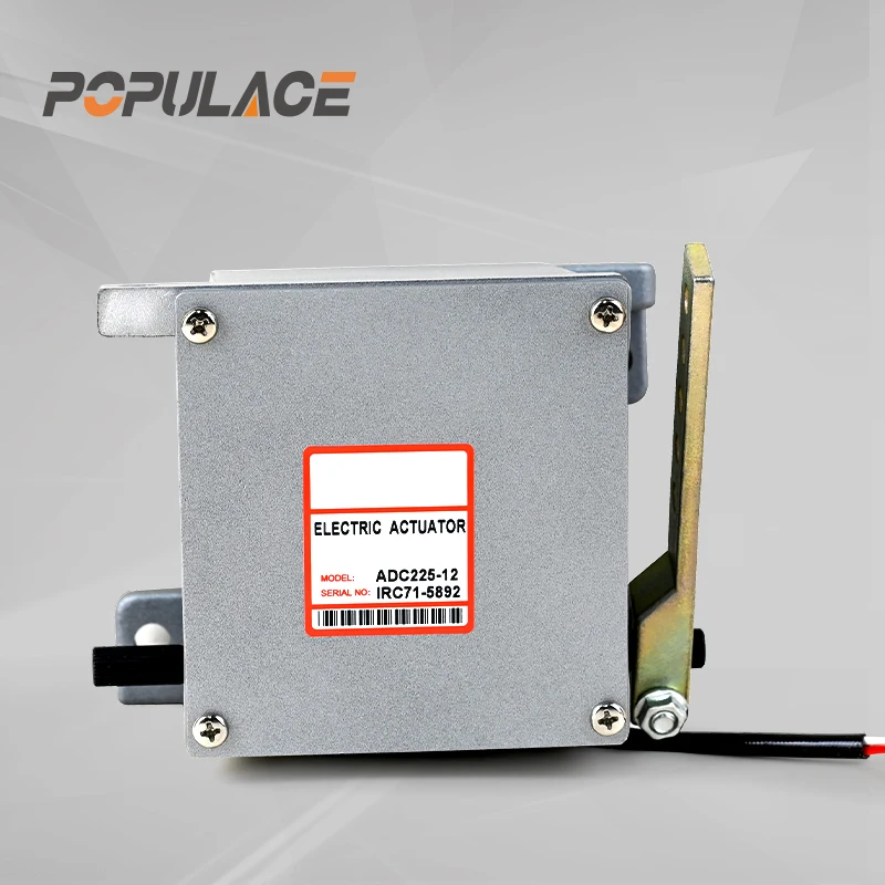
- Actuator Drive: The actuator, typically a linear solenoid or rotary motor, adjusts the fuel injection pump rack to add or reduce fuel in proportion to the error signal.
- Feedback Loop: The process repeats continuously. Most electronic engine governor units sample the MPU signal at a rate that allows response to load changes within 50–200 milliseconds.
The underlying control algorithm is typically a PID controller. Gain, stability, and droop settings in the electronic engine governor unit determine how aggressively it responds and whether it holds a fixed setpoint or intentionally allows a small speed variation at full load.
Isochronous vs. Droop Mode: Choosing the Right Setting
Mode selection is where generator commissioning decisions frequently go wrong — not because the wrong electronic engine governor was chosen, but because the operating mode was mismatched to the application.
Isochronous mode holds engine speed at a fixed nominal RPM regardless of load. For a 50 Hz generator, the electronic engine governor maintains 1500 RPM at no load and at full load alike. This mode is appropriate for a single generator powering a standalone load where precise frequency stability is the primary requirement.
Droop mode intentionally allows speed to decrease as load increases — typically 3–5%. At no load, the engine runs at approximately 1575 RPM; at full load, it settles at 1500 RPM. In parallel operation, droop mode lets each connected generator accept load proportionally without competing for the same setpoint. Each unit accepts its share based on how far its speed has dropped relative to the others.
Running two isochronous electronic engine governors in parallel without a dedicated load-sharing module typically results in one unit carrying most of the load while the other runs nearly unloaded — a configuration error that stresses components and shortens service life. For parallel applications, droop mode or a controller with integrated load-sharing capability is the standard approach.
Industrial Generators vs. Mobile Power Stations
Industrial generator sets in fixed installations — data centers, hospitals, manufacturing plants — typically run their electronic engine governor in isochronous mode with defined loads and stable environments. Speed regulation accuracy of ±0.25% is achievable with a well-tuned electronic engine governor and compatible actuator, sufficient for most grid-parallel frequency tolerance requirements.
Mobile power stations present different challenges: less predictable load profiles, varying ambient temperatures, and inconsistent fuel quality. In these environments, a kohler generator controller or deep sea electronics controller-based system often integrates governor logic within a comprehensive control architecture. External electronic governors remain the standard solution for retrofit applications and aftermarket replacements, particularly when reusing existing engine and actuator hardware.
Governor Calibration and Adjustment Steps
- Set target speed: Adjust the speed reference potentiometer on the electronic engine governor to the correct no-load RPM — 1500 for 50 Hz or 1800 for 60 Hz. Verify with a calibrated tachometer, not solely the panel frequency display.
- Adjust gain: Start at mid-range. Apply a 25% rated step load and observe response. Overshoot with slow recovery — increase gain. Oscillation — reduce gain.
- Set stability: Increase the derivative setting incrementally if hunting persists after gain adjustment. Note that faster response does not guarantee better stability — an over-damped electronic engine governor can cause sluggish load acceptance that trips sensitive downstream equipment.
- Set droop percentage: For parallel operation, set droop to 3–5%. Verify proportional load sharing by monitoring current output on each generator during a step load. The deep sea controller 4520 and comparable units include built-in droop adjustment accessible via configuration menus.
- Inspect actuator linkage: Loose actuator connections are a common source of erratic governor behavior that persists regardless of electronic calibration settings. Check for free mechanical travel and secure mounting before finalizing calibration.
Electronic Engine Governor Selection: What Technical Buyers Should Confirm
Compatibility with the existing actuator and MPU signal specification is the first filter in electronic engine governor selection — not brand preference. Confirm supply voltage (12V or 24V DC), actuator type and rated current, MPU signal voltage range, and whether the application requires isochronous or droop mode before ordering.
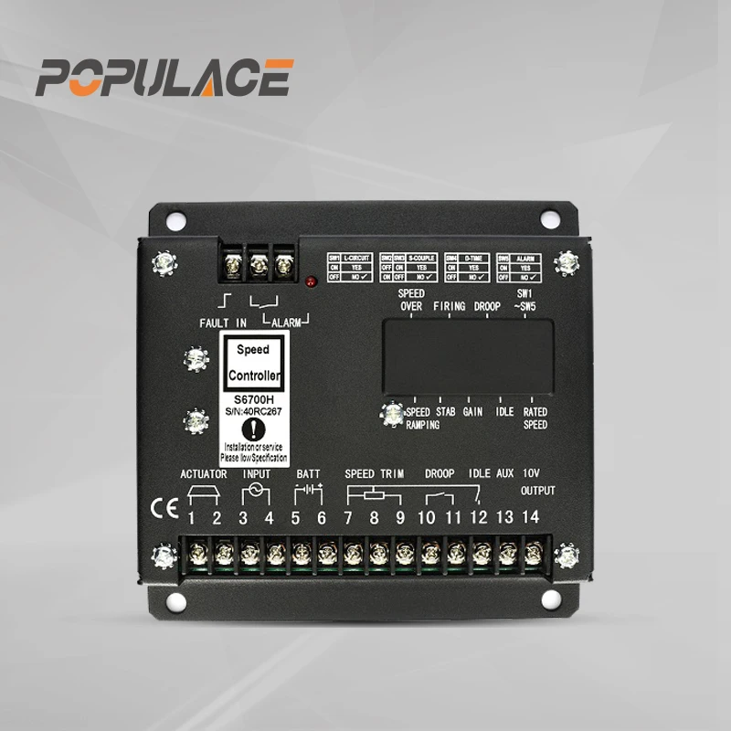
For technical procurement teams sourcing electronic engine governor units across multiple generator brands, a supplier offering pre-sales compatibility support and broad product coverage reduces sourcing complexity and post-installation risk. The S6700H Governor Speed Controller and ESD5500E Speed Governor are examples of electronic engine governor units used in both industrial and mobile power applications. Paired with compatible external actuators — including ADC120, ADC175, and ADC225 series — they form a complete electronic engine governor system for diesel engine speed control in single-unit and parallel configurations.






