
 EN
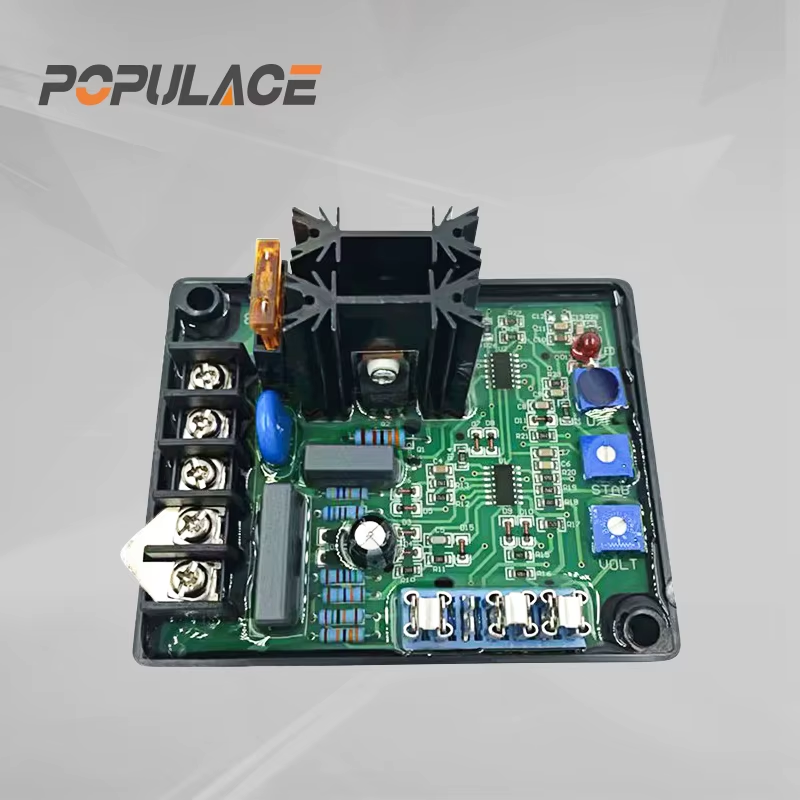
What Is the Operating Principle of a GAVR 15A Automatic Voltage Regulator?
A gavr 15a is used in a brushless generator control system to help hold alternator terminal voltage near a selected target as load changes. The useful way to understand a gavr 15a is as a closed control loop, not simply as a voltage “booster.” It senses generator output, compares that signal with a reference, changes excitation to the rotor field, and repeats the process continuously. Exact terminals, adjustment ranges, and protective functions must be confirmed against the documentation supplied for the particular unit and generator.
As a technical consultant working with generator control components, I start with compatibility and safe commissioning rather than a label alone. A gavr 15a automatic regulator may look familiar across listings, yet the sensing connection, excitation arrangement, and generator winding configuration must agree before it is energized.
The GAVR 15A Control Loop in Plain Language
The gavr 15a control loop begins with a voltage sample from the generator. The regulator conditions that sample and compares it to an internal reference that represents the desired output level. When the measured voltage is below the reference, the controller increases field excitation. More rotor magnetic field generally allows the alternator to produce more voltage. When measured voltage is above the reference, it reduces excitation. This feedback cycle is the operating principle behind a gavr-15a voltage stabilizer.
That sequence has four practical stages:
- Sensing: the regulator receives a representative generator-voltage signal through the intended sensing path.
- Comparison: electronics calculate the difference between actual voltage and the selected reference.
- Control: the circuit decides whether field drive should rise, fall, or remain close to its present level.
- Excitation output: controlled energy is delivered to the exciter-field circuit, changing alternator magnetic flux.
Because electrical loads can change quickly, the loop must be both responsive and stable. If its response is too aggressive, output may hunt or oscillate. If it is too slow, voltage can sag longer after a load step. The aim is not a dramatic correction; it is a controlled correction that settles without repeated overshoot.
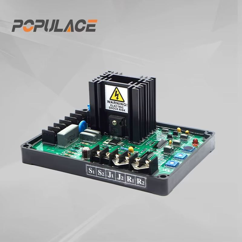
What the Sensing and Excitation Paths Need to Do
A generator avr 15a depends on two different electrical relationships: the voltage it observes and the field circuit it drives. Wiring them incorrectly can create a no-build, high-voltage, or unstable-voltage condition. Before fitting a gavr 15a, identify the generator drawing, terminal markings, rated sensing arrangement, and the required excitation path. Do not infer these connections from wire color or from a photo of another installation.
The gavr 15a circuit should be checked with the set isolated, locked out where site practice requires it, and verified dead with an appropriate meter. Inspect terminal tightness, insulation condition, earth/grounding arrangement, connector polarity where applicable, and continuity of the exciter path. A loose sensing lead can make a healthy regulator appear faulty because the controller is responding to a false measurement.
Why load behavior matters
At a stable load, a correctly matched gavr 15a automatic regulator should make small corrections. With motors, welders, or other changing loads, voltage response depends on the alternator, engine speed control, wiring, and the AVR together. A regulator cannot correct a frequency problem caused by incorrect engine speed; first confirm that frequency is at the generator manufacturer’s intended value.
Commissioning a GAVR 15A Safely
Use the published drawing for the exact gavr 15a variant and generator rather than relying on generic marketplace descriptions. With voltage adjustment set conservatively, start the generator according to site procedures and observe output using a suitable calibrated meter. Adjust only the documented voltage control, in small increments, with time for the loop to settle between changes. Record the starting position and final setting. If a stability, under-frequency, droop, or protection control is present, leave it at the documented baseline unless the generator manual calls for a change.
Do not use adjustment knobs to compensate for an unverified wiring error, a damaged winding, a failed rotating rectifier, or incorrect engine speed. This is where a gavr-15a voltage stabilizer installation often goes wrong: turning controls may temporarily alter the symptom while increasing the chance of excessive excitation or unstable operation.
Protection Behavior: Treat It as a Function to Verify
Listings may describe a generator avr 15a as having protective behavior, but the available functions and thresholds are model- and configuration-dependent. In general, an AVR may limit or reduce field drive when it detects an abnormal operating condition, but that is not a substitute for generator protection devices or documented commissioning tests. Do not claim a particular protection threshold from the “15A” label alone.
For a gavr 15a, verify the relevant manual before testing any fault-related function. If the documentation is unavailable, stop at basic wiring and voltage verification and obtain the correct diagram. Deliberately creating a fault without an approved procedure can damage the alternator, AVR, connected equipment, or personnel.
Symptom-Led Troubleshooting
| Observed symptom | Check first | Why it matters |
|---|---|---|
| No voltage build-up | Correct gavr 15a circuit wiring, residual magnetism procedure from the generator manual, exciter continuity | The AVR needs the intended sensing and excitation conditions to control field output. |
| Voltage is too high or rises uncontrollably | Sensing terminals, reference setting, engine frequency, correct AVR variant | A wrong sensed value can make the gavr 15a drive excitation in the wrong direction. |
| Voltage is low under load | Load size, engine speed, alternator condition, connections, field circuit | The cause may be outside the gavr 15a automatic regulator. |
| Voltage hunts or fluctuates | Loose terminals, load cycling, stability setting only if documented, frequency stability | Feedback loops react badly to noise, poor connections, or incorrect gain. |
When replacing a gavr-15a voltage stabilizer, compare the official diagram, sensing source, field terminals, generator type, and adjustment functions. Matching the name alone is not enough. The practical shift is to treat AVR replacement as a control-system compatibility task.
Frequently Asked Questions
Does a GAVR 15A control generator frequency?
No. A gavr 15a regulates alternator voltage through excitation. Generator frequency is primarily related to engine speed and pole configuration.
Can I adjust a GAVR 15A until any generator voltage looks correct?
No. A generator avr 15a must be wired and matched correctly first. Use only the controls and limits documented for the actual AVR and alternator.
What should I verify before replacing a GAVR 15A?
Confirm the official wiring diagram, sensing arrangement, excitation circuit, generator model, and the approved commissioning procedure. This protects both the gavr 15a circuit and the generator.
Bottom Line
The operating principle of a gavr 15a is a repeating feedback process: sense generator voltage, compare it with a reference, correct excitation, and monitor the result. Safe results depend on verified wiring, modest documented adjustments, stable engine speed, and troubleshooting the whole generator system rather than blaming the AVR first.






