
 EN
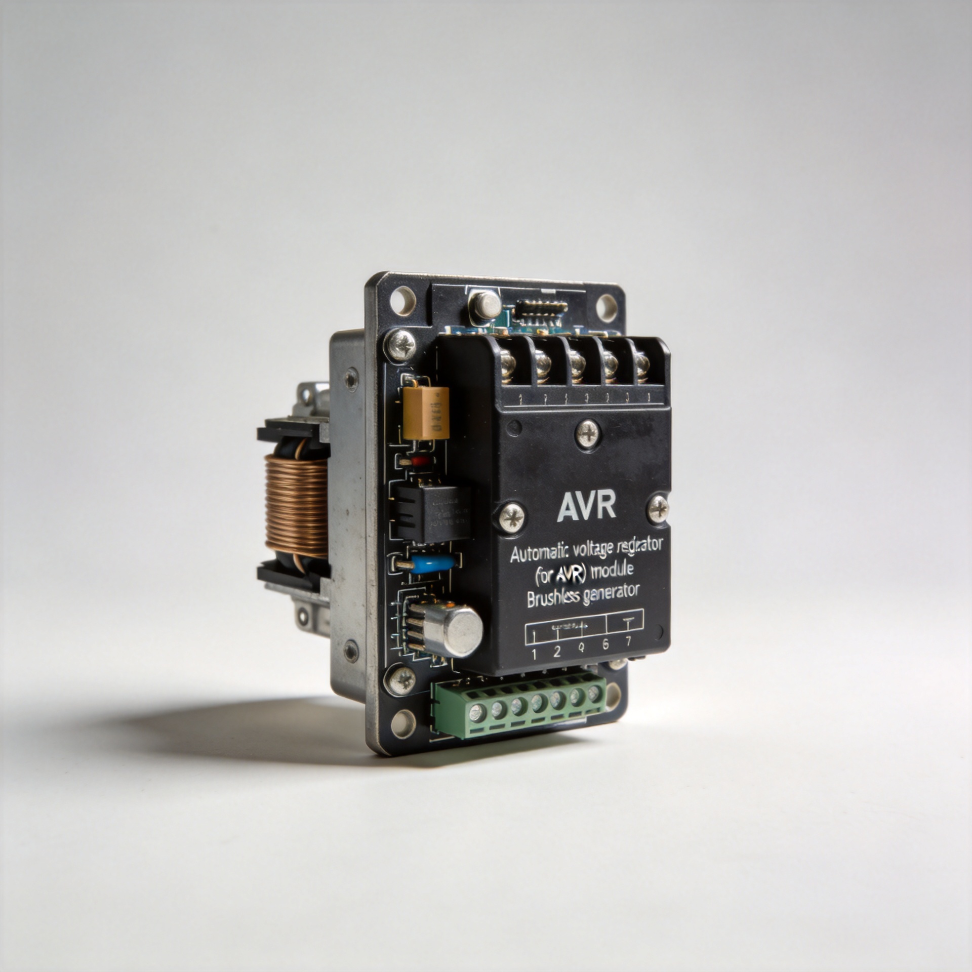
What Is the Function of a GAVR 8A AVR in a Brushless Generator?
When a brushless generator struggles to hold a steady output voltage under changing loads, the component most likely at the center of the issue is the automatic voltage regulator. The GAVR 8A AVR — specifically the GAVR-8A model — is one of the most widely used universal AVR modules for brushless generators across a range of power ratings. Understanding what it does, how it works, and what can go wrong is useful whether you are sourcing a replacement, evaluating compatibility, or troubleshooting an unstable generator output.
What the GAVR-8A Is and Where It Fits
The GAVR-8A is a half-wave phase-controlled thyristor type automatic voltage regulator. It forms part of the excitation system of a brush-less generator, sitting between the generator's sensing output and the exciter field winding. Put simply: it reads the generator's output voltage, compares it to a target reference, and adjusts the current fed into the exciter field to correct any deviation.
In a brushless generator, there are no slip rings or carbon brushes to deliver current to the rotor field. Instead, a main exciter on the same shaft generates AC current, which is rectified by rotating diodes and fed into the main rotor field. The AVR controls how much current enters the exciter field — and by extension, how much voltage the main alternator produces. The generator avr module is therefore not a passive component; it is an active closed-loop controller that keeps voltage stable across varying load conditions.
How the GAVR-8A Regulates Voltage
The operating cycle of the GAVR-8A follows a straightforward feedback loop:
- Sensing: The AVR samples the generator's single-phase output voltage at its sensing terminals. The sensing input is programmable for 110 V, 220 V, or 400 VAC via a dip-switch configuration: this is the primary adjustment needed when installing the unit on a new generator.
- Comparison: The sampled voltage is compared internally against a reference set point. If output voltage is below the set point, the AVR increases excitation current; if it is above, excitation is reduced.
- Output control: The thyristor circuit modulates the phase angle of the half-wave signal applied to the exciter field winding, controlling the average current delivered. The result is a continuous, fine-grained correction — not a simple on/off switch.
This correction loop runs continuously. That is what allows the brushless generator avr to hold output voltage within ±1% of the set point even as the load changes. In practice, ±1% on a 230 V generator means the output stays between roughly 227.7 V and 232.3 V — a level of stability that matters for sensitive electronic loads.

Key Technical Specifications
For anyone consulting a gavr 8a manual or sourcing a replacement, the core specification values are:
- Sensing input range: 110 / 220 / 400 VAC (1-phase, 2-wire), selectable via dip switches
- Continuous output current: 8 A; intermittent output: up to 10 A for 10 seconds
- Voltage regulation accuracy: ±1%
- Temperature coefficient: 0.03% per °C change in AVR ambient temperature
- Minimum residual voltage at AVR terminal: greater than 5 VAC (required for self-excitation to begin)
- Physical dimensions: approximately 12 × 9 × 6 cm; weight: 0.25 kg
An 8-amp continuous output rating gives the module its name — worth confirming against your generator's exciter field current draw under normal operating conditions. If the exciter requires more than 8 A continuously, this module is not the correct match, regardless of the voltage sensing range.
Protective and Auxiliary Features
Beyond basic voltage regulation, the GAVR-8A includes several features that affect both generator longevity and system behavior during unusual operating conditions.
Under-Frequency Protection
The GAVR-8A monitors the generator's frequency as well as its voltage. If the engine speed drops significantly — during startup, under sudden heavy loading, or when fuel supply is interrupted — the AVR reduces excitation current proportionally to prevent the generator from becoming overloaded. This protects both the exciter winding and the prime mover. Without under-frequency protection, a voltage regulator could attempt to maintain full voltage even when the engine cannot sustain full speed, drawing more field current than the exciter can handle.
Soft-Start Voltage Ramp
When the generator first comes online, the GAVR-8A ramps voltage up gradually rather than applying full excitation immediately. This reduces the mechanical and electrical stress on the alternator windings and connected equipment at the moment of energization. For generators powering motor loads — which draw high inrush current on startup — this feature reduces the likelihood of voltage dips triggering nuisance trips on downstream protection devices.
EMI Filtering
The unit includes internal electromagnetic interference filtering, which helps prevent high-frequency noise generated by the thyristor switching from feeding back into the sensing circuit. Without this filtering, spurious voltage signals could cause the AVR to oscillate or produce unstable output.
Installation Considerations and Common Pitfalls
The gavr-8a universal voltage regulator label refers to its programmable sensing range — it is not a guarantee that it will fit every brushless generator without adjustment. A few points that experienced engineers consistently flag:
Dip-Switch Configuration
The most common installation error is failing to set the dip switches correctly before powering the generator. The sensing input must match the generator's actual output voltage — connecting a unit configured for 110 V sensing to a 400 V generator will produce incorrect regulation behavior and may damage the AVR. Verify the dip-switch position against the generator's nameplate voltage before first start — this step is easy to overlook and one of the most common causes of AVR malfunction at installation.
Residual Voltage Requirement
Self-excited generators depend on residual magnetism in the rotor to initiate the build-up of output voltage. The GAVR-8A requires a minimum of 5 VAC at its sensing terminal for this process to begin. Generators that have lost residual magnetism (typically after storage, demagnetization events, or incorrect initial wiring) will not self-excite properly. The remedy is a brief flash procedure using a battery to re-establish residual magnetism in the rotor before attempting a normal start.
Ambient Temperature and Mounting
The 0.03% per °C temperature coefficient indicates that the AVR's set-point voltage will drift slightly with temperature change. In high-ambient environments — enclosures above 40°C, for example — this drift may be noticeable over time, and periodic voltage re-trimming using the onboard potentiometer may be needed. Mounting the AVR in a location with adequate airflow and away from direct heat sources reduces this drift in practice.
Sourcing and Compatibility Verification
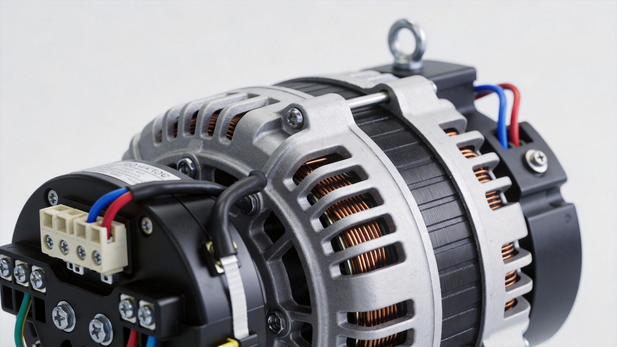
The GAVR-8A is a widely available aftermarket AVR module compatible with a broad range of brushless generator brands. For wholesalers, distributors, and maintenance teams sourcing this component, the primary verification steps are confirming the sensing voltage range, the exciter field current requirement, and the physical terminal layout against the original unit or generator wiring diagram.
Fujian Kaiyue Electronics Co., Ltd. (KYGEN Power) supplies generator AVR modules, controllers, and related parts to distributors and brand buyers across Asia, Europe, and North America. For technical inquiries or volume sourcing of the GAVR-8A and compatible brushless generator AVR modules, contact the team at kygenpower.com.
Conclusion
The GAVR 8A AVR performs a central function in any brushless generator: it continuously monitors output voltage, compares it to a reference, and adjusts the exciter field current through a half-wave thyristor circuit to maintain regulation within ±1%. Its programmable sensing input, soft-start ramp, under-frequency protection, and internal EMI filter make it suitable for a wide range of generator installations. Correct dip-switch configuration, adequate residual voltage, and attention to ambient temperature are the key installation factors that determine whether the AVR performs as specified or introduces problems from day one.






