
 EN
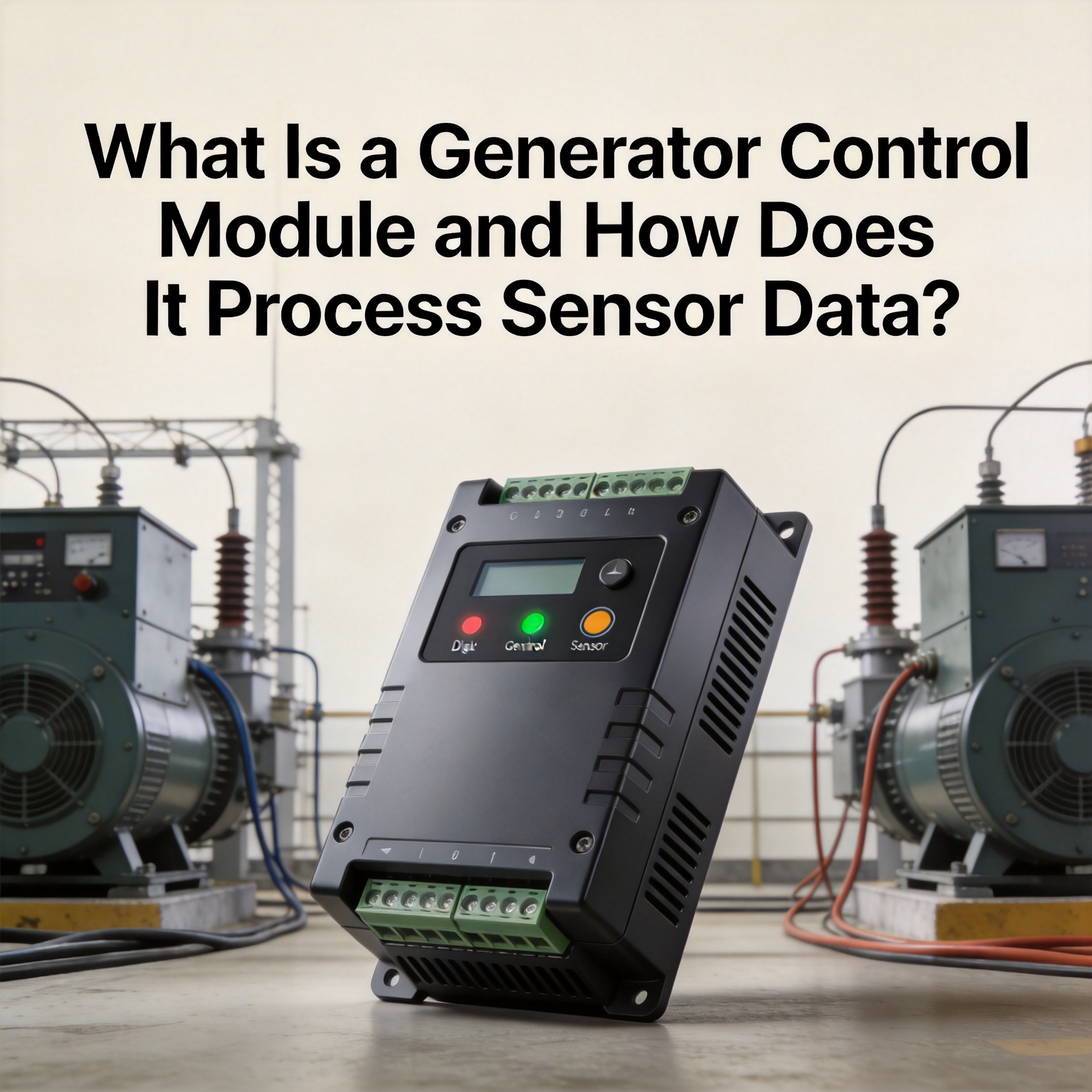
What Is a Generator Control Module and How Does It Process Sensor Data?
After enough time working with diesel generator sets, most technicians start to notice the same pattern: buyers focus on the alternator or engine, while the control module gets treated as an afterthought. That's a mistake. The generator control module is what decides whether the unit starts on command, runs within safe limits, and shuts down when something goes wrong. Understanding what it does, and how it works through the sensor data from the engine and electrical system, is relevant for anyone sourcing replacement parts, specifying a genset, or tracking down a fault.
What Is a Generator Control Module?
A generator control module is a dedicated electronic controller that monitors, manages, and protects a diesel or gas generator set during operation. Functionally, it works as a type of programmable logic controller (PLC) built specifically for genset applications. Unlike general-purpose PLCs, it arrives pre-loaded with genset logic: start/stop sequencing, load transfer handling, protection thresholds, and alarm management.
The terms generator control board, control module for generator, and digital control module genset all refer to the same component class, though the feature set varies across manufacturers and models. Simpler analog relay-based modules handle basic start/stop and overvoltage cutoff. Fully digital controllers add CAN bus communication, remote monitoring, and configurable protection curves.
A generator ECU is a related but distinct concept: it refers specifically to the engine's electronic control unit, which handles injection timing and fuel delivery on electronically controlled engines. Some digital control modules integrate ECU communication via J1939 CAN bus, linking the generator controller and the engine ECU into a shared data network.
Sensor Inputs: What the Module Reads
The module's work begins with sensor data. On a typical diesel genset, it connects to six sensor categories:
- Voltage and current sensors — track output voltage across all phases and generator current, serving as the primary electrical health indicators.
- Frequency sensor — measures engine speed indirectly through alternator output frequency. A frequency drop points to an overloaded or underspeed engine.
- Oil pressure sensor — among the most critical inputs. Low oil pressure triggers an immediate shutdown in nearly every control module configuration.
- Coolant temperature sensor — monitors engine temperature and initiates shutdown if overheating is detected.
- Fuel level sensor — tracks tank level and provides early alarms before a fuel-out shutdown occurs.
- Engine speed sensor (RPM) — on electronically governed engines, the control module reads RPM directly to detect overspeed conditions.
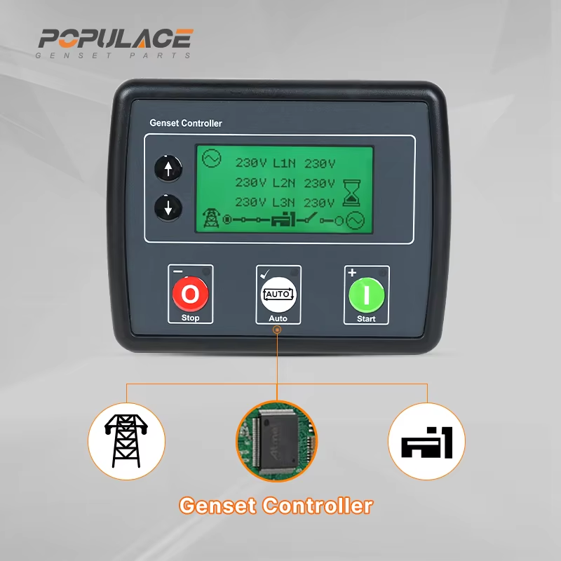
On older generators, sensors feed analog voltage signals directly to the module's input terminals. On modern gensets with a generator ECU, sensor data travels over a CAN bus network, and the control module reads interpreted data packets rather than raw analog signals.
How the Module Processes Sensor Data
The processing chain inside a digital control module genset follows four stages: acquire, convert, compare, and act.
Signal Acquisition and Analog-to-Digital Conversion
Analog sensor signals, typically 0–5V or 4–20mA depending on sensor type, feed into the module's input channels. The onboard microprocessor samples these signals at regular intervals, commonly every 100ms or faster for protection-critical inputs, and converts them to digital values through an analog-to-digital converter (ADC). Modules with CAN bus interfaces skip the ADC stage for networked sensors and receive pre-converted digital values directly.
Threshold Comparison
Once digitized, each sensor reading gets compared against pre-configured thresholds. Factories typically set these to standard defaults, for example a low-oil-pressure shutdown at roughly 0.5–1.0 bar, and technicians can adjust them through the module's parameter interface. If a reading crosses a defined limit, the module flags the condition and passes it to the decision stage.
Decision and Output Command
The module's control logic maps each flagged condition to a response: a warning alarm, a timed shutdown, or an immediate emergency stop. The distinction between alarm and shutdown matters in daily operation. A high-temperature warning typically activates an alarm output and an LED on the generator control board, but lets the genset keep running. A critically low oil pressure reading does the opposite: the module cuts the fuel solenoid and starter circuit immediately, with no delay for load status.
On gensets with Auto Mains Failure (AMF) functionality, the module also reads mains voltage from an external input. When mains voltage drops outside acceptable parameters, the AMF sequence starts: the module initiates the genset start cycle, monitors output frequency and voltage coming up to stable levels, then commands the automatic transfer switch to move the load. Depending on module configuration and engine crank time, this sequence typically completes within 10 to 30 seconds.
Analog vs. Digital Control Modules: A Practical Distinction
The gap between analog and digital generator control boards goes deeper than the feature list. Analog modules use relay logic and comparator circuits. Protection thresholds are set with physical potentiometers; the processing is electronic rather than software-based. They're straightforward and durable, but they offer no flexibility after commissioning and no event logging.
Digital control modules, which now dominate in current genset installations, use microprocessors and firmware-defined logic. They support configurable parameters, event logs, serial or CAN communication, and, in advanced models, remote access via GPRS or Ethernet. The tradeoff is complexity: a digital module needs correct firmware configuration and is more sensitive to compatibility issues with specific engine platforms.
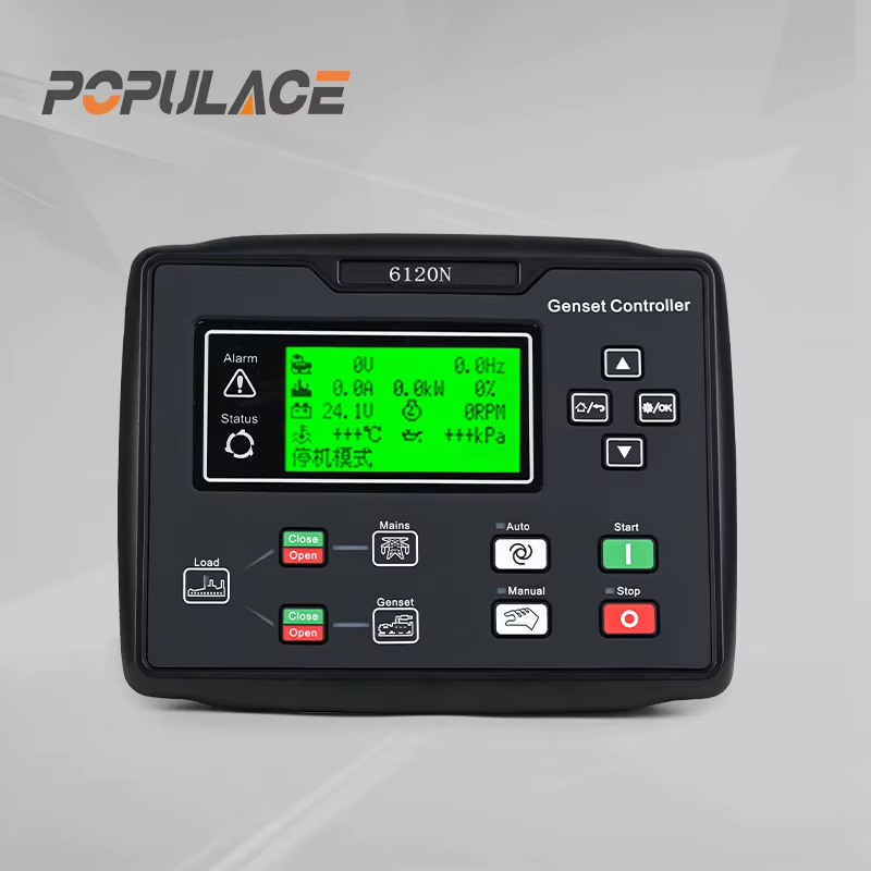
Compatibility is where buyers run into the most trouble. A control module for generator replacement isn't a matter of matching connector pin counts. You need to verify voltage input range, sensor signal types, communication protocol support (particularly on engines with an ECU), and protection logic defaults. Assuming cross-compatibility between module models from different manufacturers, even within the same product family, is a common and avoidable sourcing mistake.
What to Know When Sourcing a Replacement Module
When replacing a generator control module, the sensor interface specifications carry as much weight as the module's feature list. A module rated for 12V analog sensors won't read a 24V system accurately. One without J1939 CAN support can't communicate with a Cummins QSX engine ECU. Confirming these details before placing an order, rather than discovering the mismatch on arrival, saves both time and cost.
Suppliers who provide clear compatibility data, including input voltage range, sensor signal types, and engine protocol support, make the sourcing decision considerably easier. For a component sitting at the center of the generator's protection system, technical documentation is the clearest signal that a part will actually work in the intended application.
Summary
A generator control module is the decision layer of a diesel or gas genset. It reads sensor data from the engine and electrical system continuously, converts analog signals to digital values, compares readings against thresholds, and translates fault conditions into protection actions: alarms, controlled shutdowns, or emergency stops. Digital control modules extend this with AMF/ATS logic, CAN bus communication with the generator ECU, and field-adjustable parameters. Knowing how this processing chain works helps buyers select the right replacement module and gives maintenance engineers a clearer starting point when diagnosing control-related faults.






