
 EN
What Is a Diode Rectifier and How Does It Work in a Generator?
A generator may produce useful AC at its main output terminals, but several parts inside the machine need controlled DC to create and regulate the magnetic field. That is where a Diode Rectifier becomes important. In a brushless alternator, a rotating diode assembly commonly turns AC from the exciter rotor into DC for the main rotor. In a control circuit, a smaller rectifier function may also supply or process power for an AVR.
As a technical consultant working with generator control components, I start with compatibility rather than a part number alone. A diode can look simple, yet its polarity, mounting, thermal path, current capability, reverse-voltage requirement, and place in the excitation circuit all matter. This guide explains the principle first, then connects it to practical generator troubleshooting and replacement decisions.
What a Diode Rectifier Does
A diode is a semiconductor device that strongly favors current flow in one direction. When AC changes polarity, a single diode conducts during the half-cycle in which it is forward biased and blocks during the opposite half-cycle. A rectifier circuit arranges one or more diodes so the load sees current with one polarity rather than alternating polarity.
In the familiar bridge arrangement, four diodes route both halves of an AC waveform to the same positive and negative output terminals. This is why a bridge rectifier for generator applications is often described as a full-wave rectifier: it makes use of both halves of the AC input. The output is pulsating DC, not automatically smooth battery-quality DC. Filtering and regulation depend on the rest of the circuit.
The key idea is not that a Diode Rectifier creates energy. It changes the form and direction of available electrical energy so another winding or circuit can use it correctly. That distinction helps prevent a common troubleshooting mistake: replacing diodes when the real fault is an exciter winding, a loose connection, or an AVR sensing problem.
How Rectification Fits into a Brushless Generator
In a typical brushless generator, the automatic voltage regulator supplies controlled excitation to a stationary exciter field. The exciter rotor then produces AC. A rotating rectifier assembly, mounted on the rotating shaft, converts that exciter AC into DC for the main rotor field winding. As the main rotor turns inside the stator, the generator produces the AC delivered to the load.
- AVR control: The regulator senses generator voltage and adjusts excitation according to its design.
- Exciter generation: The exciter rotor develops AC as it rotates in the exciter field.
- Rotating rectification: The diode pack changes that AC into DC for the main rotor.
- Main alternator output: The energized main rotor creates the magnetic field that induces AC in the stationary stator windings.
This path explains why the rotating components deserve careful attention. A failed generator rectifier diode can reduce field current, distort the excitation balance, or prevent voltage from building as expected. The symptom may look like low output voltage, unstable voltage, or no voltage, but the symptom alone does not identify the failed part.
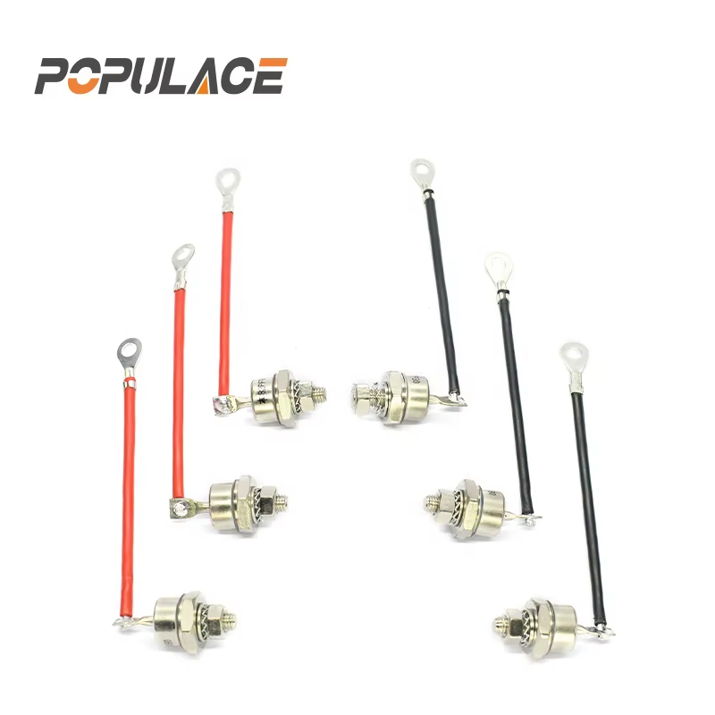
Rotating Rectifier Assembly Versus an AVR Rectifier Module
These names are sometimes used loosely, although they refer to different locations and jobs. A rotating diode pack is part of the mechanical rotating assembly and usually serves the main rotor excitation path. It must withstand rotational forces and shed heat through its mounting arrangement. By contrast, an avr rectifier module refers to rectification within, or associated with, the voltage-regulation electronics. The AVR is stationary and its exact circuit varies by generator design.
| Component | Typical location | Primary role | Replacement focus |
|---|---|---|---|
| Rotating diode assembly | On the rotating exciter/main rotor assembly | Converts exciter AC to main-rotor DC | Polarity, diode type, heat sinking, mounting, wiring |
| AVR rectifier function | Stationary regulator circuit | Supports control/excitation circuitry | Correct AVR model, sensing and supply arrangement |
| External bridge rectifier | Stationary panel or auxiliary circuit | Converts AC for a dedicated DC load | Terminal layout, AC/DC connections, electrical rating |
Early in sourcing, buyers often focus on voltage and frequency ratings. After a failed installation, the focus usually shifts to polarity marks, terminal arrangement, shaft-side mounting, and the actual wiring diagram. That is the more useful mindset for a generator part that must fit a specific alternator design.
What Happens When a Generator Rectifier Diode Fails?
A diode can fail open, fail short, or develop a poor connection. An open diode removes one intended current path. A shorted diode can create an abnormal path and may stress related windings or electronics. Heat damage, vibration, incorrect installation torque, contamination, and an electrical surge can all contribute, but a visual inspection does not prove the failure mode.
Before replacing a diode, isolate the generator, follow the manufacturer’s safety procedure, and discharge stored energy where applicable. A meter’s diode-test setting may help compare devices, but testing a diode while it remains connected can give misleading readings because parallel circuit paths influence the result. The service documentation for the alternator should determine the correct isolation and test method.
Useful diagnostic observations
- Compare the physical condition of each diode, lead, terminal, and heat-sink contact.
- Check for loose hardware, overheated insulation, cracked solder joints, or reversed connections after prior service.
- Verify the excitation circuit in sequence instead of assuming every low-voltage condition is a diode fault.
- Confirm whether the fault appears under no load, at a particular load, or after the unit warms up.
If a generator runs at a stable load, a component issue may appear consistently. If the load swings frequently, however, verify the whole regulation loop as well; a diode replacement will not correct a mismatched AVR setting or a poor sensing connection.
How to Select a Replacement Diode Rectifier
For wholesalers, brand owners, and maintenance teams, the most reliable request is based on the alternator model and the existing assembly—not on a generic phrase such as “rectifier diode for generator.” Gather the original part markings, alternator model, wiring layout, photos of both sides of the assembly, and the exact number of diodes. A component-level review reduces the chance of receiving a part with an incompatible interface or sensing arrangement.
- Electrical direction and polarity: Confirm which terminals are anode and cathode and how the positive and negative diodes are arranged.
- Electrical class: Match the required forward-current and reverse-voltage capability specified for the alternator design; do not substitute an unverified rating.
- Mechanical interface: Check stud size, lead style, mounting plate, spacing, and clearance for the rotating assembly.
- Thermal path: Diodes rely on good contact with the heat-dissipating structure. Damaged mounting surfaces or unsuitable compound can shorten service life.
- Assembly balance: When a pack uses matched positive and negative devices, follow the manufacturer’s replacement guidance rather than mixing unknown parts.
Price is a starting point, but the practical cost usually comes from whether the part is genuinely compatible with the generator variant. A supplier focused on generator control components can help organize compatibility checks, yet the final selection should still be validated against the machine documentation and the application’s operating conditions.
Bottom Line
A Diode Rectifier in a generator converts AC into the DC needed by a field or control circuit. In a brushless alternator, the rotating diode assembly is the link between exciter AC and main-rotor DC; a bridge rectifier for generator auxiliary circuits or an AVR rectifier module may serve a different location and purpose. Understanding that path makes fault finding more systematic and replacement sourcing more accurate.
For a replacement inquiry, provide the generator or alternator model, existing diode markings, clear assembly photos, wiring information, and the observed fault. Those details are more useful than a generic part description and help a technical review focus on compatibility before the order is placed.






