
 EN

What Is a Deep Sea Engine Controller and How Does It Protect the Engine?
A deep sea engine controller is the decision-making unit in a generator or engine-driven system. It receives status signals, applies the configured start, run, warning, and shutdown logic, and commands outputs such as the starter, fuel solenoid, alarm, and load-control circuit. In practical terms, it is not just a display: it is the layer that decides when an engine may start, what conditions are acceptable while it runs, and when a fault requires an alert or a stop.
The name is often used loosely. A deep sea engine control module can refer to a controller for a generator set, pump, compressor, or other engine application. Exact functions depend on the model, configuration, connected sensors, and whether the engine communicates through an ECU. For that reason, a controller should be evaluated as part of a complete control system rather than as an interchangeable panel component.
What the controller does during a normal operating cycle
A typical sequence begins with a remote-start signal or a manual command. The controller checks permissives, energizes preheat or fuel outputs where configured, cranks the engine, and looks for a valid running indication. After the engine reaches a stable state, it can observe engine inputs and, on generator applications, electrical values such as voltage and frequency. When a stop command arrives, it removes or changes the run command, observes whether the engine comes to rest, and may apply a cooldown timer.
This sequence matters because protection is timed as well as measured. Oil pressure is expected to be low before an engine has started. A correctly configured controller therefore uses a start-safety or alarm-inhibit interval so it does not trip immediately during cranking. Once the engine is running, the same input can become a valid protection signal. The correct delays and thresholds must come from the engine documentation and the application requirements, not from another installation’s settings.
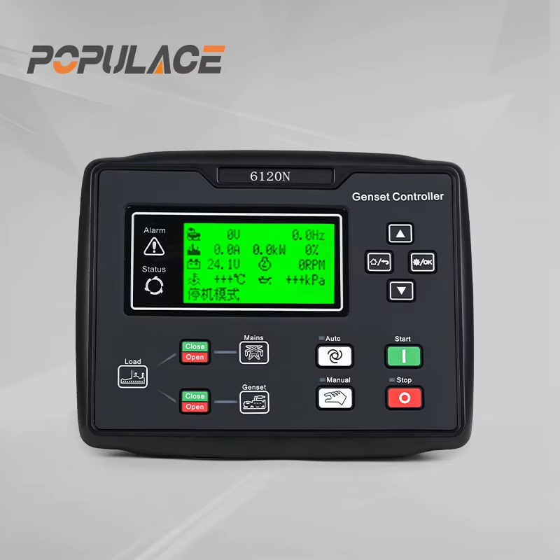
How a deep sea engine controller protects the engine
Protection logic generally separates warnings from shutdowns. A warning tells an operator that a condition needs attention while allowing the engine to continue if that is appropriate. A shutdown commands a stop or locks out the system because continuing to run could cause damage or create an unsafe condition. Many controllers retain a shutdown indication until the fault is corrected and the unit is deliberately reset.
- Low oil pressure: after the running delay, a low pressure switch or sender can initiate a warning or shutdown.
- High coolant temperature: temperature inputs can trigger an early warning and, at a higher configured level, a shutdown.
- Overspeed or loss of speed signal: depending on the speed-sensing method, the module can react when engine speed is outside the allowed range.
- Emergency stop: this is commonly wired as a fail-safe circuit so a broken connection is treated as a stop condition.
- Fail to start or fail to stop: the logic can limit crank attempts and report an engine that still appears to be running after a stop command.
- Generator-side faults: an engine generator controller deep sea configuration may also supervise voltage, frequency, phase conditions, or load-transfer interlocks.
These protections reduce exposure to known abnormal conditions; they do not replace routine maintenance or a proper mechanical inspection. A controller can only act on the signal it receives and the logic it has been configured to apply.
Sensors and wiring: where many false faults begin
When a controller reports a fault, the engine is not automatically the failed component. An open circuit, a loose terminal, an incorrect sensor type, a poor common return, or the wrong input polarity can produce a reading that looks like a real fault. This is especially important for oil-pressure and coolant-temperature circuits, where the controller may be configured for a resistive sender, a normally open switch, a normally closed switch, or a user-defined analogue input.
During installation, follow the module wiring diagram and the engine’s sensor specifications. Confirm the DC supply, fuse protection, terminal torque, sensor return path, shielding approach for speed pickup wiring, and separation of low-level sensor wiring from high-current cables. Do not use a sensor’s thread sealant in a way that unintentionally isolates an earth-return sensor from the engine block. For CAN-connected engines, verify the required network connections, termination, and ECU configuration before diagnosing a controller setting.
For a dse engine controller or any comparable module, the safest diagnostic order is simple: read the active alarm, verify the physical condition it names, inspect the sensor and harness, compare the input type and polarity with the configuration, then test the signal according to the approved manual. Resetting an alarm repeatedly without identifying the cause can hide a developing wiring or engine problem.
Configuration and commissioning essentials
Configuration turns generic hardware into a controller for one specific engine and duty. At minimum, the technician should verify battery voltage range, engine speed source, start and stop output behavior, alarm delays, sensor curves or switch polarity, remote-start logic, and any generator AC sensing arrangement. If a setting is not understood, it should be checked against the model-specific manual and the engine or alternator documentation rather than copied from a similar panel.
- Record the engine model, system voltage, sensor types, and intended operating mode before loading or editing settings.
- With the engine disabled from starting by an approved method, prove the start sequence and output logic where safe to do so.
- Confirm that displayed readings are plausible before allowing load transfer or unattended operation.
- Test warning and shutdown paths only through an approved commissioning procedure, with personnel, isolation, and reset arrangements in place.
- Document the final configuration file, wiring changes, alarm thresholds, and test results for later service work.
Some buyers search specifically for a deep sea 5500 controller. That phrase should lead to a model-by-model check, not an assumption about features. Compare the required input count, output type, engine interface, AC measurement needs, enclosure fit, communications, and the availability of the correct documentation for the exact unit under consideration.
Service diagnostics and buyer evaluation
A useful first distinction is whether the issue is a real process fault, a bad signal, an output problem, or a configuration mismatch. For example, low oil pressure after start may require an engine check, but it can also point to a sender, harness, or polarity setting. A no-crank condition can involve the battery, safety circuit, starter output, start command, or an inhibited permissive. Start with the displayed event and the wiring diagram, then test one link in the chain at a time.
For buyers, compatibility documentation is often more valuable than a broad feature list. Ask for the exact model reference, supported supply voltage, input and output schedule, connection diagram, configuration software or access method, and the revision of the applicable manual. Also confirm whether the controller is intended for an electronic ECU engine, a conventional engine, a generator set, or an engine-only application. A suitable fit is the unit whose functions, interfaces, and service information match the installation—not simply the unit with the most options on paper.
Conclusion
A deep sea engine controller protects an engine by turning sensor data and operating commands into disciplined alarm and shutdown decisions. Reliable results depend on accurate sensor selection, sound wiring, sensible delays and thresholds, and a documented commissioning process. Treat the controller as part of the engine-control system, verify every critical interface, and use the exact model documentation before changing protection settings.





