
 EN
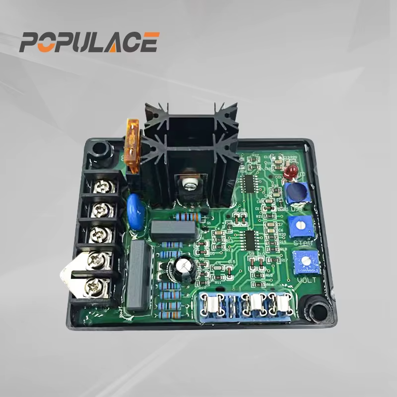
The Voltage Regulation Circuit of an AVR 15A Explained.
When a brushless generator produces voltage that wanders as the load changes, the automatic voltage regulator is often the first component people suspect. That is reasonable, but it helps to understand what the board is actually doing before changing settings or ordering a replacement. An avr 15a is part of a closed control loop: it reads generator voltage, compares that reading with a target, and changes excitation so the alternator can move back toward the target.
This explanation applies to the common GAVR-style 15a automatic voltage regulator family used on some brushless alternators. Terminal labels, input ranges, adjustment names, and protection behavior differ by model. Treat the wiring diagram supplied for the exact regulator and alternator as the controlling document.
The short version: sensing, comparison, and excitation
An AVR does not stabilize voltage by absorbing excess output like a household power conditioner. It controls the magnetic field that makes the alternator generate voltage. In simplified form, the circuit follows this sequence:
- A sensing circuit samples the generator’s AC output.
- A reference circuit establishes the requested voltage level.
- An error amplifier compares the measured value with that reference.
- A control stage changes current delivered to the exciter field.
- The alternator output changes, and the sensing circuit measures the result again.
That loop repeats continuously. If output falls below the target, the regulator normally increases field excitation. If output rises above the target, it reduces excitation. The important point is that an avr 15a generator application involves both the board and the alternator system around it: sensing wires, windings, rotating rectifier parts, field circuit, engine speed, and load all influence what the regulator sees.
What is inside the voltage regulation circuit?
1. The AC sensing and power-input section
The sensing section receives an AC signal from the alternator. Depending on the design, that signal may also provide operating power for the regulator. It is usually conditioned before the control electronics use it: the circuit limits, rectifies, filters, or scales the incoming waveform so a low-voltage control stage can read it safely.
This is why the sensing connection deserves more attention than many installers give it. A loose terminal, damaged sensing lead, incorrect terminal selection, or a winding voltage outside the board’s permitted range can make a healthy regulator behave incorrectly. Simpler version: if the AVR reads the wrong voltage, it will make the wrong correction.
2. The reference and error-amplifier section
Inside an avr 15a, a stable reference is compared with the scaled sensing signal. The difference is the error signal. A positive error means the measured output is lower than the target; a negative error means it is higher. The voltage-adjust potentiometer changes the requested reference point, not the generator’s mechanical speed.
That distinction matters during troubleshooting. Raising a voltage trim can conceal a sensing or excitation problem for a moment, but it cannot repair an open field path or a badly mismatched sensing arrangement. Adjust only after confirming the alternator is at rated speed and the manual allows adjustment under the present conditions.
3. The driver and field-output section
The controller’s low-power error signal cannot energize the exciter field directly. A driver stage therefore switches or modulates a higher-current path to the field. Common regulator designs use semiconductor devices and rectification arrangements to turn available AC into controlled DC field current. By changing the effective field current, the regulator changes magnetic flux and therefore the alternator’s generated voltage.
The “15 A” in a 15 amp avr description is generally associated with the regulator’s field-output capability, subject to the manufacturer’s stated duty conditions and cooling assumptions. It is not a statement that the generator can supply only 15 A to the load, nor is it enough to establish compatibility by itself. Field resistance, excitation topology, sensing range, alternator rating, and supply arrangement still need to match.
4. Stability and protection functions
A voltage loop that reacts too slowly can allow noticeable dips and rises; one that reacts too aggressively can hunt or oscillate. Many regulator families therefore include stability, damping, or response adjustments. Some also provide under-frequency roll-off, soft-start behavior, or protection functions. Their availability and labels are model-dependent, so do not assume that a similarly shaped board has the same settings.
Under rapidly changing loads, field response in actual service can differ from bench behavior. Heat in windings, reactive loads, non-linear loads, and engine-speed changes all affect the system. If the voltage swings only when a large motor starts, the finding may point to load dynamics or engine response rather than a failed AVR alone.

How the feedback loop reacts to common conditions
| Observed condition | What the circuit normally tries to do | What to verify first |
|---|---|---|
| Voltage is low at correct speed | Increase field excitation | Sensing input, field continuity, brushes or rotating rectifier parts where applicable |
| Voltage is high at correct speed | Reduce field excitation | Voltage-adjust setting, sensing wiring, reference/control fault |
| Voltage hunts up and down | Continuously correct a changing error | Stability setting, load changes, loose sensing connections, engine governor behavior |
| Voltage falls with frequency | May reduce output intentionally on units with under-frequency protection | Engine speed and the regulator’s frequency-related setting |
These are diagnostic directions, not a remote diagnosis. A regulator can be operating logically on a bad measurement, and a generator can have an AVR fault only after the surrounding circuits have been checked.
Why a generator voltage stabilizer 15a is not automatically interchangeable
Listings often describe a unit as a universal generator voltage stabilizer 15a. “Universal” should be read cautiously. It may mean the board is intended to cover a range of common brushless-generator arrangements, not that it will safely replace every regulator with a 15 A marking.
- Confirm the sensing-voltage range and the actual alternator terminals used for sensing.
- Confirm the excitation supply and field-output requirements.
- Confirm the generator’s nominal frequency and the under-frequency configuration, if fitted.
- Compare terminal designations and wiring function—not terminal position or board appearance alone.
- Check whether the alternator uses brushes, a rotating rectifier assembly, permanent-magnet excitation, or another arrangement.
The pitfall that gets overlooked most often with AVRs is not the nameplate output voltage; it is the sensing input range. That range can vary with winding configuration and may not be obvious in a short catalog description. Whether a replacement will work on a particular set depends on details a catalog photograph cannot confirm.
A safe troubleshooting sequence before replacing the AVR
Disconnect and isolate the generator according to the equipment procedure before touching terminals. Generator circuits can retain hazardous energy and can cause injury or equipment damage. If qualified testing is not available, involve a generator service technician.
- Verify speed and frequency first. Voltage regulation assumes the alternator is operating at the intended speed. A speed problem can look like a voltage problem.
- Inspect the sensing and field wiring. Look for heat damage, loose fasteners, corrosion, and connectors with poor contact. A replacement board cannot correct a high-resistance connection.
- Check the AVR’s documented input and field specifications. Compare them with the alternator documentation before applying power.
- Measure only with appropriate instruments and procedures. Record voltage and frequency at no load and through controlled load changes where the service procedure permits.
- Make one documented adjustment at a time. Mark the original position of voltage or stability controls. Do not turn several controls at once.
- Evaluate the whole excitation path. If field current cannot reach the exciter or the rotating components are defective, changing the AVR may not resolve the symptom.
Practical takeaway
An avr 15a regulates a generator through feedback, not by a fixed output setting. Its circuit senses alternator voltage, compares that signal to a reference, and controls field excitation until the error is reduced. Once that loop is clear, troubleshooting becomes more disciplined: verify speed, sensing, wiring, field path, and compatibility before blaming the board.
For buyers and maintenance teams, the most useful avr 15a replacement question is not simply “Is this a 15 A AVR?” It is “Does this regulator’s sensing, excitation, frequency, and terminal arrangement match this exact alternator?” An avr 15a should be specified by function and wiring, not board appearance. Before commissioning an avr 15a, document the original terminal arrangement and settings. If the installed avr 15a still produces unstable voltage after those checks, test the entire excitation path rather than replacing parts by trial. That extra check is usually faster than correcting a mismatched installation later.





