
 EN

The Internal Circuitry of an AVR Electrical Generator Explained
An avr electrical generator does not hold voltage steady by magic. It uses a closed feedback loop: it observes the alternator output, compares that reading with a target, and changes excitation until the difference becomes small. That is the useful mental model whether you are troubleshooting a failed set or checking a replacement part. Terminal labels, sensing ranges, and excitation arrangements vary by model, so work from the correct wiring diagram and isolate the machine before testing.
Where the AVR sits in an electrical generator
In an avr electrical generator, the regulator is normally a stationary electronic module connected to the alternator terminals and to the excitation circuit. The rotor carries the magnetic field; the stator produces the usable AC output. When load rises, terminal voltage tends to sag. The AVR responds by changing field energy so the alternator can recover toward its setpoint. This is why an electrical generator AVR is part of the excitation system, not a substitute for the engine governor: the governor manages speed and frequency, while the AVR manages voltage.
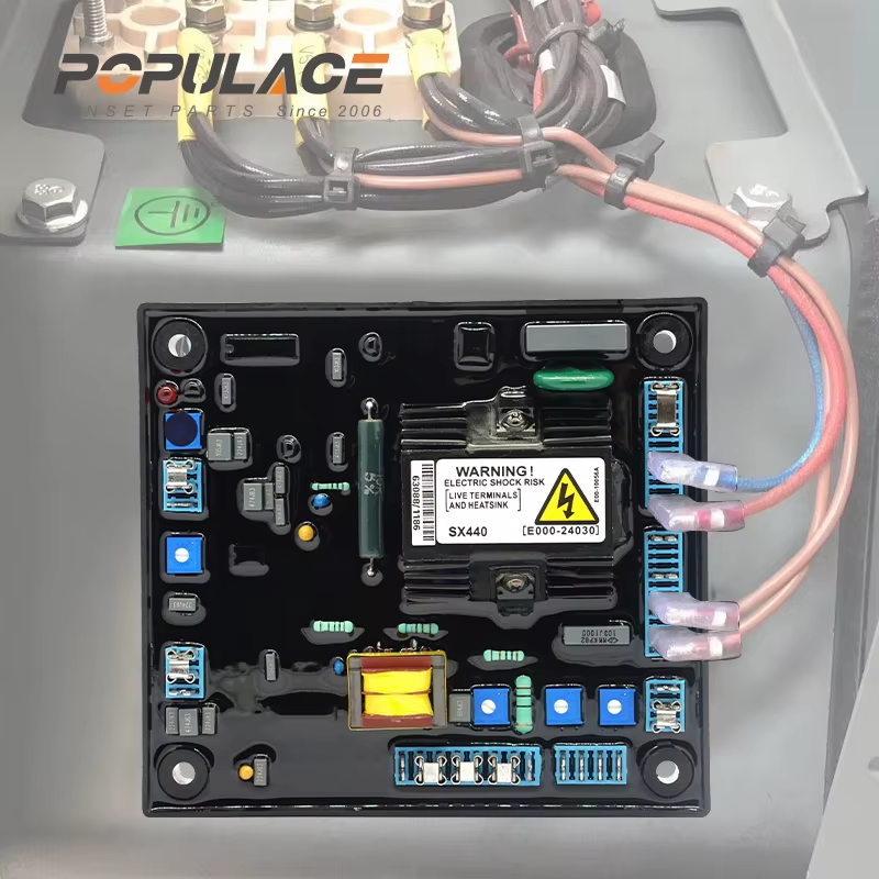
A typical avr electrical generator has four functional blocks: voltage sensing, reference and error processing, a power output stage, and protection or adjustment circuits. The board may look simple, but each block relies on compatible input and output conditions.
1. Voltage sensing: the feedback path
The sensing input is the starting point for every avr electrical generator control cycle. Leads from the generator output supply a scaled representation of terminal voltage to the board. A resistor network, transformer, or other conditioning components reduce and shape that signal before it reaches low-voltage electronics. The regulator compares the measured value with an internal reference. If the sensed voltage is below target, the control loop calls for more excitation; if it is above target, it reduces excitation.
This is one reason a generator voltage regulator unit cannot be selected by physical size alone. A board intended for one sensing range can misread another alternator’s output. Before replacing an AVR for electric generator service, verify the sensing connection, nominal system voltage, phase arrangement, and the manufacturer’s approved terminal scheme.
2. Reference, comparator, and control section
Inside the avr electrical generator, a stable reference creates the “wanted” voltage. A comparator or error amplifier evaluates the gap between that reference and the sensed voltage. The resulting error signal is filtered and amplified so the regulator does not chase every brief waveform disturbance. In older analogue boards, this work is commonly performed by discrete resistors, capacitors, diodes, transistors, and an integrated control circuit. In other designs, a digital controller may perform part of the decision-making.
Capacitors matter here because they shape response. Too little filtering can make an avr electrical generator hunt or oscillate; too much can make recovery sluggish. That does not mean a technician should change component values casually. The correct response setting depends on the alternator, exciter, load behavior, and the original design.
3. Power stage: turning a small command into field current
The control signal in an avr electrical generator is low power, but the exciter field requires controlled energy. The power stage performs that conversion. Depending on the design, it may use rectifier diodes, transistors, SCRs, or other semiconductor switching devices to supply regulated DC to the stationary exciter field. The exciter then creates magnetic flux that is transferred through the rotating assembly and ultimately influences the main generator field.
This signal path explains a common misunderstanding: the AVR does not directly “make” the output AC. It changes excitation, and the alternator’s magnetic system produces the resulting change in terminal voltage. A bridge rectifier or related rectification section may appear in or around the excitation path, but the exact topology is model-specific. Treat a board’s terminal markings and schematic as authoritative rather than assuming every avr electrical generator is wired alike.
4. Adjustment and protection circuits
Most AVR boards include a voltage trim potentiometer. Some add stability, droop, under-frequency roll-off, or remote-adjust inputs. These features let an avr electrical generator behave predictably across its intended operating envelope. Under-frequency roll-off is especially important conceptually: when engine speed falls, the regulator may intentionally limit excitation rather than demand field current that the machine cannot support at reduced speed.
Protection parts can include fuses, surge suppression, current limiting, reverse-polarity safeguards, and thermal protection. A failed protection component can make a generator voltage regulator unit appear dead even when the main control circuit is intact. Look for visible damage, but do not rely on appearance alone; electrical checks must be performed with safe procedures and the right meter.
A practical signal-path check
When an avr electrical generator has low or unstable voltage, follow the energy path rather than guessing:
- Confirm engine speed and frequency are within the machine’s specified operating condition.
- Verify the alternator’s sensing voltage reaches the correct AVR terminals.
- Check plugs, terminals, fuses, and wiring for heat damage, corrosion, or loose connections.
- Compare the AVR field output and resistance checks with the manufacturer’s service data.
- Only then assess the board, exciter field, rotating diodes, and main alternator as a system.
For an electrical generator AVR replacement, record the original part number, sensing arrangement, field supply requirements, connector pinout, adjustment features, and alternator model. Early in sourcing, buyers often focus on a voltage label. After an unsuccessful installation, the focus shifts to sensing input type, connector pinout, and excitation compatibility. Those deeper details determine whether avr generator spare parts are actually interchangeable.
What the internal circuit does not control
An avr electrical generator is not responsible for every power-quality symptom. Frequency errors usually lead back to engine speed or governor behavior. Harmonic distortion may involve alternator design, nonlinear loads, wiring, or load conditions. Repeated tripping can involve protection devices external to the AVR. Separating these functions keeps diagnosis efficient and prevents replacing a generator voltage regulator unit for a fault it cannot correct.
Key takeaway
The internal circuitry of an avr electrical generator is usefully understood as a feedback loop: sense terminal voltage, compare it with a reference, condition the error, and regulate excitation. That sequence is straightforward; compatibility is where the practical work begins. For any avr electrical generator, use the specific alternator documentation, observe electrical safety practices, and confirm the full sensing-to-field path before fitting replacement parts.





