
 EN

How to Test an Automatic Voltage Regulator for Generator Before Use
Anyone who maintains generators regularly has seen this pattern: a generator that runs fine for months suddenly puts out unstable voltage. Equipment gets damaged. Downtime follows. Eventually someone checks the automatic voltage regulator for generator and finds the problem was right there, quietly developing, before the unit was even put into service.
Testing an AVR before installation is not a complex process, but it does require the right steps — and a bit of patience. This guide covers what to check, how to do it with basic tools, and what the results should look like on a functioning unit.
What an Automatic Voltage Regulator Does — and Why Testing Matters
The automatic voltage regulator for generator systems is a solid-state electronic device that senses output voltage and adjusts excitation current to the alternator's field winding. When load increases and voltage tends to drop, the AVR compensates. When load drops and voltage would rise, it pulls back. The goal is a steady output — typically within a narrow tolerance around the rated voltage.
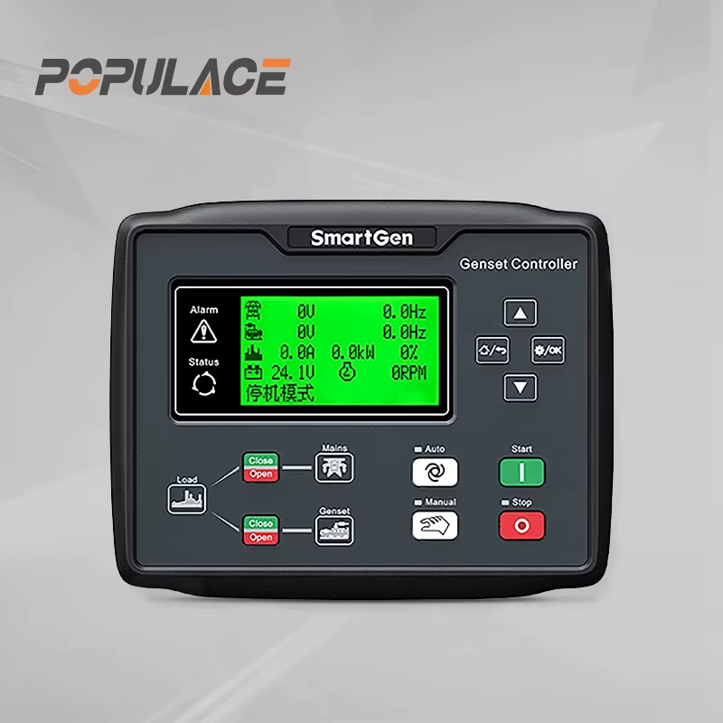
AVR failure is one of the most common causes of generator voltage instability. Even a new AVR pulled from storage can develop internal faults — from damaged components during shipping, moisture exposure, or electrostatic discharge. Checking an AVR before use catches those problems early rather than after the unit is installed and running under load.
There is an important caveat here: testing with a standard multimeter has real limits. You can check for continuity, basic resistance, and diode condition. You cannot fully simulate the operating electrical conditions the AVR will see in service. So the tests described here are pre-installation screening, not a complete certification of function.
What You Need Before Starting
Before you begin, gather the following:
- A digital multimeter with AC/DC voltage, resistance (Ω), and diode test functions
- The AVR wiring diagram or installation guide for the specific model
- The generator's rated output voltage and frequency specifications
- Anti-static handling precautions — generator AVR components are sensitive to electrostatic discharge
One thing many technicians skip is reading the model-specific documentation. The generic testing procedure below applies broadly, but terminal pinouts, resistance ranges, and sensitivity pot positions vary between AVR models. Getting the wiring diagram from the supplier before testing saves time and reduces the risk of misreading results.
Step-by-Step Testing Procedure
Step 1: Visual Inspection
Before connecting any test equipment, inspect the AVR physically. Look for:
- Burnt or discolored components on the board
- Cracked or damaged solder joints
- Corrosion or moisture deposits on terminals
- Physical damage to the potentiometer or trim pots
If any of these are present, the unit should not be installed regardless of subsequent test results.
Step 2: Continuity and Resistance Check (Multimeter in Ω Mode)
Set your multimeter to resistance mode (Ω). With the AVR disconnected and unpowered:
- Check for continuity between terminals that should be connected according to the wiring diagram
- Measure resistance between the voltage sensing input terminals — compare against the specified range in the documentation
- Check resistance between the field output terminals
An open circuit where continuity is expected, or a very high resistance reading on a low-resistance terminal pair, can indicate an internal fault. Short circuits between terminals that should be isolated are also a failure sign.
Step 3: Diode Inspection
Many AVR boards include internal rectifier diodes. Use your multimeter's diode test function to check each accessible diode:
- Forward bias should show a voltage drop in the range of 0.4V to 0.7V depending on the diode type
- Reverse bias should show overload (OL) or infinite resistance — no current should flow
A diode that reads near-zero in both directions is shorted. A diode that shows OL in both directions is open. Either condition means the AVR is faulty and should not be used.
Step 4: Output Voltage Check Under Running Conditions
This step requires the AVR to be installed and the generator running — it is not a bench test. Once connected:
- Set your multimeter to AC voltage
- Connect the probes to the generator's main output terminals
- Start the generator at no-load
- A 120V-rated system should read between 115V and 125V under stable conditions
- For 230V systems, acceptable range is typically 220V to 240V
If voltage is significantly above or below the rated range, adjust the voltage trim pot on the AVR according to the documentation. If voltage fluctuates continuously, or the AVR does not respond to adjustments, the unit may be defective.
Step 5: Load Test Observation
Apply a known load to the generator and observe the voltage reading. The automatic voltage regulator for generator systems should compensate quickly — you may see a brief dip when load is applied, but voltage should stabilize within a few seconds. Persistent voltage droop under load, or voltage swings that do not settle, suggest either an AVR problem or a mismatch between the AVR sensitivity setting and the generator configuration.
Common Test Results and What They Mean
When testing generator avr automatic units in the field, a few patterns come up repeatedly. Voltage that is stable at no-load but drops sharply under load often points to incorrect AVR gain or stability settings — not necessarily a defective unit. Voltage that is stable under load but drifts at no-load can indicate a sensitivity trim that needs adjustment.
AVR voltage drift is a known behavior with older or improperly stored units. If you observe the output voltage slowly climbing or falling over several minutes with constant load, the internal reference components may have degraded. This is worth noting especially if the unit has been in storage for an extended period.
For avr for generator replacements, matching the replacement unit's voltage and frequency rating to the original specification is critical. Installing a unit with a slightly different sensing voltage range — even within the same model family — can produce output that appears acceptable on initial test but fails to regulate correctly under variable load conditions.
When to Involve a Specialist
Standard multimeter testing covers the basics, but it does not replicate operating electrical conditions. For generator avr automatic units used in critical applications — standby power for hospitals, data centers, or industrial facilities — a specialist with a generator test bench can perform a more complete functional evaluation.
The same applies when you are evaluating an automatic voltage stabilizer generator for the first time from a new supplier. A bench test can confirm that the unit regulates across the full load range, responds within specification to load transients, and does not exhibit instability at specific frequency or temperature conditions.
Practical Notes for Wholesale Buyers
For wholesale and distribution buyers sourcing generator voltage regulator components, pre-use testing procedures like these matter at a batch level as well as for individual units. Receiving a batch that passes initial inspection and shows no obvious physical defects is a starting point — but spot-testing a sample from each shipment, using the steps above, adds another layer of incoming quality control.
One commonly overlooked issue is identifying the exact AVR model installed on a generator when original documentation is missing. Part number markings on the board can sometimes be compared against manufacturer cross-reference charts, or the original installation records. Attempting to test or replace an AVR without confirming the correct model risks installing a compatible-looking but functionally mismatched unit.
For sourcing inquiries or technical compatibility support on automatic voltage regulator for generator applications, having a supplier who can provide wiring diagrams and model-specific installation guidance alongside the component is worth the extra effort to find.
Summary: Pre-Use AVR Testing Checklist
Before connecting any AVR to a generator, work through this sequence:
- Visual inspection for physical damage, burns, corrosion
- Continuity and resistance check per wiring diagram (multimeter in Ω mode)
- Diode test for each accessible rectifier diode (forward drop 0.4–0.7V, reverse OL)
- Output voltage measurement at no-load after installation (115–125V for 120V systems)
- Voltage stability check under known load with trim adjustment if needed
These steps take less time than diagnosing voltage problems after the generator is in service. And for any unit that fails at any stage, the right answer is straightforward: do not install it.





