
 EN

How to Test a Single Phase Bridge Rectifier for Generator AVR Systems?
A generator that will not build voltage, hunts at the output, or loses excitation under load can lead technicians toward the AVR. Before replacing the regulator, test the single phase bridge rectifier that feeds or supports its excitation path. A bridge fault can mimic an AVR fault, while a wiring or measurement mistake can make a good part look bad.
As a technical consultant working with generator control components, I start with isolation and terminal identification rather than a quick continuity beep. The goal is to test the diodes inside the single phase bridge rectifier one at a time, with the generator safely stopped and the circuit disconnected as required by its documentation.
What the bridge rectifier does in an AVR circuit
A single phase rectifier bridge uses four diodes to steer both halves of an AC waveform into one DC polarity. Depending on the generator design, that DC may supply an excitation-related circuit, a sensing-related circuit, or another controlled AVR path. The enclosure commonly has two AC terminals, often marked ~, plus a positive + and negative − terminal.
A common misunderstanding is that every generator AVR rectifier can be checked while it remains fully wired. In practice, parallel components can create alternate current paths and distort a diode-mode reading. If the service procedure allows it, isolate the bridge terminals or remove the rectifier for a clearer test. Photograph or label every conductor before disconnecting it.
Safety first: make the circuit testable
- Stop the generator, disable automatic start, and follow the site lockout/tagout procedure.
- Disconnect the battery or control supply as the equipment manual requires.
- Verify that the circuit is de-energized before using diode mode. Capacitors can retain charge even after power is removed.
- Use insulated probes and avoid touching exposed terminals together.
- Do not use resistance or diode mode on an energized AVR circuit.
If the alternator or AVR has a manufacturer-specific test sequence, use that sequence first. Terminal labels, sensing arrangements, and protective parts are not identical across generator models.
Tools and preparation
You need a digital multimeter with a diode-test function, insulated probes, a wiring diagram or terminal photo, and a way to mark leads. Set the meter to diode test, not continuity. Continuity mode can be useful for finding a dead short, but its result is less informative than the voltage-drop direction reported by diode mode.
Locate the two AC inputs and the DC + and − outputs. If a package is unmarked, do not guess from wire color. Trace the wiring diagram, compare the physical pin layout with the part marking, or obtain the verified component documentation before proceeding.
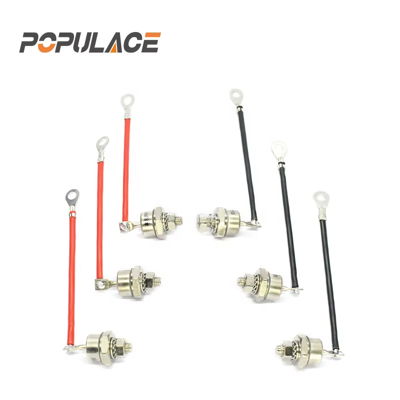
How to test a single phase bridge rectifier step by step
1. Check each AC terminal to the positive terminal
Place one probe on an AC ~ terminal and the other on +. Reverse the probes and record both readings. Repeat at the other AC terminal. Each path should behave like one diode: a measurable forward-voltage reading in one direction and OL, or an equivalent open indication, in the other direction.
2. Check each AC terminal to the negative terminal
Repeat the process from each AC terminal to −. The probe direction that produced a forward reading in the previous checks will not necessarily be the same here. What matters is consistent one-way conduction for each diode path, not forcing every measurement to display the same number.
3. Compare the four diode paths
For a silicon 1 phase bridge rectifier, a typical forward reading is often roughly 0.4 to 0.7 V, while the reverse direction should show open circuit. Treat that as a diagnostic pattern, not an absolute specification: meters use different test currents, and temperature or built-in protection parts can affect the displayed value. Four broadly similar directional results are more meaningful than one isolated decimal value.
4. Check for obvious terminal shorts
A reading near zero or a continuity beep in both directions across one diode path suggests a shorted diode. OL in both directions where the other comparable paths show a normal forward reading suggests an open diode or a poor probe connection. Recheck with clean probe contact and a known-good meter before condemning the bridge.
Reading results on a generator AVR rectifier
| Observed pattern | Likely interpretation | Next action |
|---|---|---|
| One forward reading and one open reading on all four paths | The diode pattern is broadly normal | Continue with AVR inputs, sensing, exciter, and wiring checks. |
| Near-zero reading or beep in both directions on a path | Possible shorted diode | Isolate the bridge further and retest; replace the matched assembly if confirmed. |
| Open reading in both directions on one path | Possible open diode, bad connection, or incompatible test setup | Verify terminal mapping and probe contact, then retest out of circuit. |
| All results are inconsistent | Parallel circuitry, charge, loose leads, or incorrect terminal identification | Discharge safely, isolate as permitted, and check the wiring diagram. |
Why a bad bridge can resemble an AVR failure
A failed generator avr rectifier can remove part of the rectification path or leak current in the wrong direction. The visible symptom may be low output voltage, unstable excitation, a no-build condition, or an AVR that appears unresponsive. Those symptoms are not proof that the bridge is defective; excitation windings, sensing leads, residual magnetism, connectors, and the AVR itself can produce similar behavior.
That is why replacement should be based on a complete pattern: confirmed terminal identification, repeatable out-of-circuit diode readings, inspection for heat damage or cracked terminals, and the correct part number or electrical rating for the generator. Part compatibility matters more than a similar-looking package.
Practical retest and replacement checklist
- Record each diode-mode result and the probe orientation.
- Inspect terminals for looseness, corrosion, discoloration, or overheated insulation.
- Confirm the replacement single phase diode bridge matches the original terminal layout and verified electrical requirements.
- Reconnect leads exactly as documented, keeping AC and DC terminals in their original positions.
- After reassembly, perform the generator manufacturer’s controlled start-up and voltage checks.
For wholesalers and service teams, keeping the original markings, generator model, AVR model, and test record with the failed part prevents a repeat mismatch. A reliable supplier can help confirm compatibility, but the final selection still depends on the specific generator and excitation arrangement.
Conclusion
Testing a single phase bridge rectifier is a focused way to separate a diode fault from a broader AVR problem. De-energize the circuit, identify the two AC and two DC terminals, test all four directional diode paths, and interpret the results as a consistent pattern. If readings remain unclear, isolate the bridge more completely or use the generator manufacturer’s service guidance before replacing parts.





