
 EN
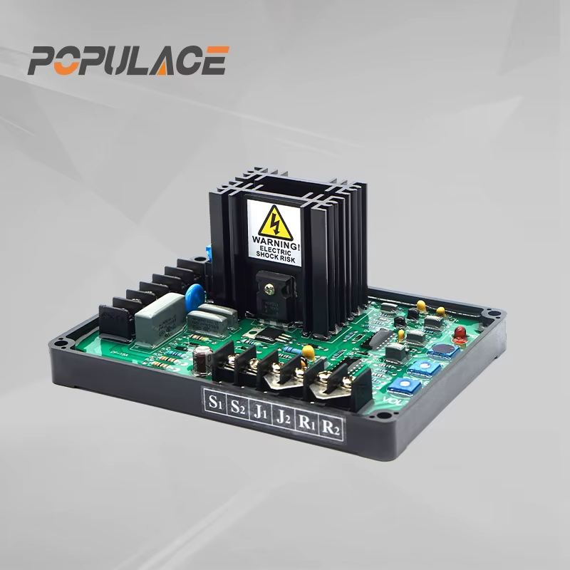
How to Test a GAVR 8A AVR Before Installing It on a Generator
When a standby generator fails to produce stable voltage, the first thing I check is whether the AVR is the original spec — or a substitute that was installed without proper pre-commissioning. A surprising number of field callbacks trace back to an AVR that passed a visual check but was not bench-tested before installation. If you are working with a GAVR 8A unit, thirty minutes of bench testing before connecting it to your generator can save hours of troubleshooting.
The GAVR 8A is a universal 8-amp, half-wave self-excited, dip-switch programmable automatic voltage regulator designed for brushless generators. This GAVR-8A AVR supports sensing input of 110, 220, or 400VAC (1 phase, 2 wire) and delivers continuous output of 8 amps — with a 10-second intermittent burst capacity of 10 amps. Those numbers matter when you are confirming test results with a multimeter. If the readings do not align with the datasheet, do not guess — investigate.
Why Testing a GAVR 8A Matters Before Installation
The GAVR 8A is used in a wide range of brushless generator applications because of its programmable voltage settings and compact design. But being a compact, affordable small generator AVR also means it sometimes arrives with dip switches misconfigured or with transit damage not visible on the surface. A basic pre-installation test catches those issues before the unit is bolted to a generator panel.
If you do not have the datasheet, the GAVR 8A datasheet confirms: sensing input at 110/220/400VAC, continuous output current at 8A, and voltage regulation accuracy at less than 1% under normal engine governing. Keep those numbers visible while you work.
Tools and Materials You Need
- Digital multimeter (with AC/DC voltage, resistance, and diode test modes)
- The GAVR 8A unit, its wiring diagram, and the datasheet
- A small variable bench power supply (optional but useful for active output testing)
- Anti-static mat or grounded wrist strap
- Magnifying glass or loupe for component-level visual inspection
Step 1: Visual Inspection
Start with what you can see. Physical damage to electronic control components may not appear immediately after installation — it can surface after weeks of runtime. Before picking up a probe, check the following on your GAVR-8A AVR:
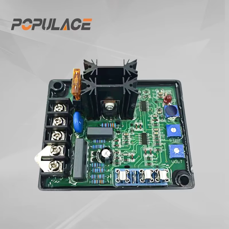
- Board surface: Look for burn marks, cracked components, or discoloration around the rectifier section
- Fuse: The GAVR 8A has a built-in high-capacity 8A fuse. Confirm it is intact and seated correctly
- Dip switches: Verify all switches are accessible and in a clear position — not damaged, bent, or stuck between states
- Terminal block: Check for bent pins, corrosion, or residue from prior wiring
- Physical dimensions: The GAVR-8A measures 107.0mm (L) × 82.0mm (W) × 50.0mm (H). If the unit is warped or compressed, reject it before testing
Electrostatic discharge damage during transit may not produce visible marks. If the GAVR 8A arrived without anti-static packaging, flag that during inspection and proceed to electrical tests with extra care.

Step 2: Verify Dip-Switch Configuration
The GAVR 8A uses dip switches to program sensing voltage and operating frequency. Setting them incorrectly before installation is one of the most common causes of immediate voltage instability after startup. Before the unit reaches the generator, confirm the switch positions match your application:
- Sensing voltage selection: Switch positions 5–6 set 220V or 110V input; switch 7–8 selects 50Hz or 60Hz operation
- Under-frequency protection: On a 60Hz system, the factory-preset knee point is 55Hz. On a 50Hz system, it is 45Hz. Confirm the frequency setting matches the generator's output
- External voltage adjustment: If a 1K ohm trimmer is connected to terminals 2–1, set it to the midpoint before testing the GAVR-8A
A misconfigured dip switch can look like an AVR failure and lead to an hour of unnecessary diagnosis. For this 8 amp voltage regulator generator application, verify the switch positions before proceeding to electrical tests.
Step 3: Resistance and Continuity Check
Set your multimeter to resistance mode (Ω). This test checks the internal windings and connections of the GAVR 8A before any power is applied.
- Disconnect the GAVR-8A AVR from any circuit
- Measure resistance between field output terminals F+ and F−. A healthy unit shows a low but non-zero resistance consistent with field winding impedance. An open circuit (∞) or dead short (near zero) indicates a fault
- Check continuity from the input terminals (sensing voltage pins) to confirm there are no open traces on the board
- Run a continuity check across the fuse terminals. A blown fuse reads open; a good fuse reads near zero
If you see erratic or inconsistent readings on the GAVR 8A in resistance mode, the unit may have moisture damage or a partially failed component. Document the reading and contact your supplier before proceeding.
Step 4: Diode and Rectifier Inspection
Switch your multimeter to diode test mode. The GAVR 8A uses an internal rectifier to convert AC sensing input to regulated DC field output. A failed diode is one of the more common failure modes in this type of small generator AVR, particularly in units that experienced electrical surge or reversed polarity during a prior installation.
- Identify the rectifier bridge on the GAVR-8A board — typically a four-diode bridge near the power input side
- Test each diode in forward bias: a healthy diode should read approximately 0.4–0.7V forward and OL (open loop) in reverse
- A reading near zero in both directions indicates a short; OL in both directions indicates an open. Either result means the GAVR 8A should not be installed
Step 5: Bench Input Voltage Test
This test confirms the GAVR 8A responds correctly to an applied sensing voltage. You will need a controlled AC voltage source matched to the unit's power input range of 100–260VAC.
- Apply sensing voltage to the appropriate input terminals based on your dip-switch configuration
- Set your multimeter to DC voltage mode and probe the F+ and F− terminals of the GAVR-8A
- The unit should produce a DC output that ramps up to the field voltage target within approximately 2 seconds (soft start). If the output climbs immediately to full value without ramping, the soft-start function may be damaged
- At 240VAC input, maximum output at the field terminals should reach approximately 90VDC. Confirm your reading is within a reasonable range of this figure
The GAVR 8A voltage regulation accuracy is specified at less than 1% under 4% engine governing — a tight target. If your bench test shows voltage fluctuating beyond a few percent under a stable input, the unit's internal regulation components may be degraded. An 8 amp voltage regulator generator application depends on that kind of stability from the start; installing a marginal unit simply defers the problem.
Step 6: Confirm Thermal and Environmental Suitability
The GAVR-8A is rated for −40°C to 65°C with a vibration tolerance of 3G at 100–2000 Hz. Confirm the mounting location inside the generator enclosure does not exceed these limits during extended runtime. Thermal drift on the GAVR 8A is 0.03% per degree Celsius — worth noting if the installation site runs near the upper limit.
Signs the GAVR 8A May Be Faulty
After running these tests, reject the GAVR-8A before installation if you observe any of the following:
- Open circuit or dead short at F+ / F− in resistance mode
- Blown or missing 8A fuse
- Any diode reading zero in both polarities (shorted) or OL in both (open)
- No soft-start ramp during bench input voltage test
- Field output voltage significantly outside expected range
- Visible burn marks, cracked components, or displaced dip switches
Most of these issues indicate the GAVR 8A was damaged before it reached you — which is a supplier conversation, not a repair task. A reliable supplier of GAVR-8A AVR components should provide documentation and be willing to process a replacement for units that fail bench inspection.
Final Check Before Generator Installation
If the GAVR 8A passes all tests above, you have confirmed the unit is electrically sound and correctly configured. Before mounting:
- Re-verify dip-switch positions against the target voltage and frequency
- Confirm the external trimmer (if used) is at the midpoint starting position
- Review the wiring diagram one final time against the generator's field and stator connections
Thirty minutes of pre-installation testing is considerably less disruptive than diagnosing unstable output after the generator is back in service. The GAVR 8A is a capable and widely used AVR in the brushless generator market — when it is working correctly and correctly configured, it should deliver stable regulated voltage with minimal ongoing attention. That reliability starts with the pre-installation verification covered here.





