
 EN
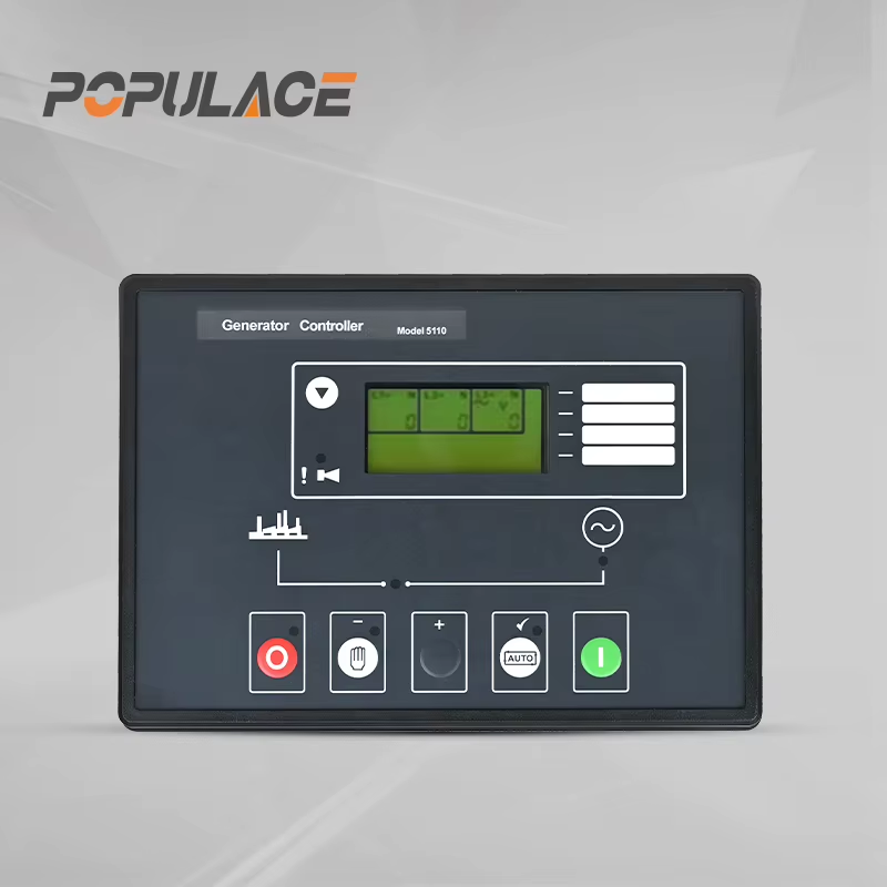
How to Source Generator Speed Controller Units for Genset Manufacturing?
For a genset manufacturer, sourcing a generator speed controller is not a matter of choosing a board with the right connector. The unit sits in a control loop that includes the engine, actuator, magnetic pickup or speed sensor, fuel system, alternator, and load profile. A controller that appears compatible on a bench can still cause hunting, slow recovery, frequency dip, or unstable operation once it is installed on a finished set.
The practical approach is to qualify the generator speed controller as an interface-and-performance package. Start with engine facts, define the load-response requirement, then ask the supplier to prove the configuration with documented tests. This reduces late-stage calibration work and makes repeat manufacturing more predictable.
Begin with the engine and governing architecture
Before requesting quotations, write a one-page application sheet for each engine family. Identify the rated speed and frequency, fuel type, cylinder count, existing mechanical governor arrangement, actuator type, and the available speed-feedback method. These details determine whether an electronic speed governor controller can operate the intended system without an adapter or a redesign.
- Speed reference: state the target governed speed, idle and rated-speed requirements, and whether the set will run at 50 Hz, 60 Hz, or both.
- Speed pickup: document whether the input is a magnetic pickup, Hall sensor, or another signal; include expected signal range and connector arrangement.
- Actuator: provide the actuator model, coil resistance or rated current, travel direction, linkage arrangement, and return-spring behavior.
- Power and grounding: specify nominal battery voltage, cranking-voltage conditions, fuse expectations, chassis grounding, and harness length.
- Operating environment: include enclosure conditions, vibration exposure, temperature range, and any marine, mobile, or standby-duty constraints.
Ask the supplier to respond against this sheet rather than simply confirm that its generator rpm controller is “universal.” A documented compatibility matrix is more useful than a broad marketing claim because it exposes whether a different actuator current range, sensor interface, or wiring scheme is required.
Check actuator and sensor compatibility as a pair
An electronic governor is only as stable as the feedback and output devices around it. For actuator compatibility, compare continuous and peak current capability, output type, and polarity with the actuator data. Confirm that the controller can drive the actuator through the full operating range without excessive heating. Also review what happens at power loss: the engine should move to the intended safe fuel position through the complete linkage, not only on a disconnected bench test.
For speed feedback, verify tooth count or pulses per revolution, pickup gap guidance from the sensor maker, shielding needs, and the controller’s acceptable input range. A noisy or intermittent speed signal can look like a tuning problem. During qualification, have the supplier show the actual signal quality at cranking, idle, rated speed, and load transitions. This step is particularly important when a speed control for generator application uses long harnesses or shares routing with starter and charging circuits.
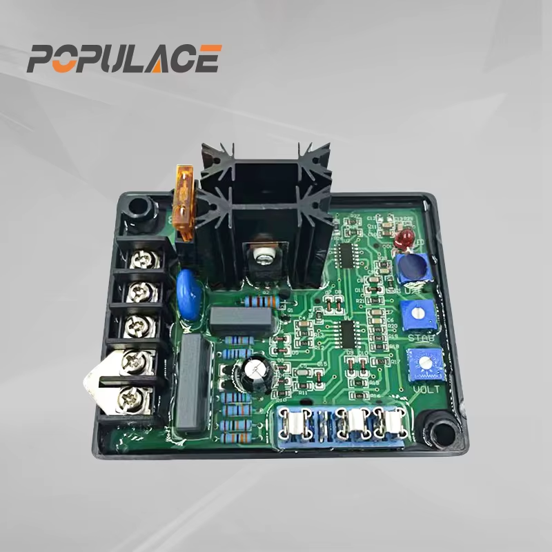
Specify load response instead of asking for “fast response”
Fast response is meaningful only when it is tied to an application. Define the largest planned load step, the expected recovery behavior, the frequency tolerance, and whether nonlinear loads or motor starts are common. A good sourcing brief separates steady-state governing accuracy from transient behavior after a step load is applied or removed.
ISO 8528-5 is a useful reference when discussing genset transient performance because it categorizes generator sets from G1 to G4, with G4 based on user-specified requirements. It does not make a controller automatically suitable, but it gives engineering teams a shared vocabulary for acceptance targets. Put the selected set-level target in the purchase specification and require the supplier to state the test conditions behind its response claim.
For each proposed generator speed controller, request a tuning method that identifies gain, stability, droop or isochronous mode, and any speed-ramp settings. The supplier should explain which parameters are adjustable, who controls revision changes, and how a production line can load the approved configuration without relying on individual technician judgment.
Build a repeatable acceptance test
Qualification should include more than a visual inspection and power-on check. Use a representative engine, actuator, sensor, and harness whenever possible. Record the controller serial number, firmware or configuration revision, test equipment, ambient conditions, and results. A simple acceptance sequence can include:
- Confirm pinout, supply polarity, fuse protection, and grounding before energizing the unit.
- Run cranking and start tests to confirm that the actuator moves correctly and speed feedback is acquired reliably.
- Verify idle, rated speed, and no-load stability after warm-up.
- Apply agreed load steps and record frequency change, recovery trend, overshoot, and any visible hunting.
- Repeat after a short heat-soak or vibration exposure where the application demands it.
- Save the approved parameter file and define pass/fail limits for future incoming inspection.
This process gives purchasing and engineering a common decision record. It also makes it easier to compare a substitute engine speed controller genset unit if availability changes later.
Ask for quality documentation that supports traceability
A reliable supply program needs documents that connect the approved sample to production shipments. Request a controlled datasheet, wiring diagram, version history, incoming and functional test records, packing identification, and a process for handling nonconforming units. If the supplier performs final functional testing, clarify what inputs and outputs are checked and whether the test record can be linked to a lot or serial number.
For a generator rpm controller, revision control matters as much as the initial sample. A component substitution, firmware adjustment, or changed calibration range can alter behavior even when the enclosure and label look unchanged. Agree on a written change-notification period and define whether your engineering team must approve changes before shipment.
Evaluate supply continuity before release
Once technical qualification is complete, assess whether the source can support your production plan. Discuss forecast windows, minimum order quantities, lead-time assumptions, safety-stock options, and how shortages will be communicated. Keep an approved configuration record, a controlled wiring reference, and a small buffer of validated units for field service and pilot builds.
It is also sensible to maintain a second-source evaluation path, but do not assume one electronic speed governor controller is interchangeable with another. Repeat the interface and load-response checks for any alternate. The cost of a controlled second-source trial is usually lower than the cost of an emergency change during a production interruption.
Turn sourcing into a controlled engineering decision
A sound generator speed controller sourcing decision joins purchasing discipline with governing-system validation. Define the engine interface first, verify the actuator and sensor as a matched pair, set measurable transient targets, and retain test and revision records. When these requirements are built into the RFQ and acceptance plan, a speed control for generator unit becomes a repeatable component of your genset platform rather than a recurring troubleshooting risk.






