
 EN
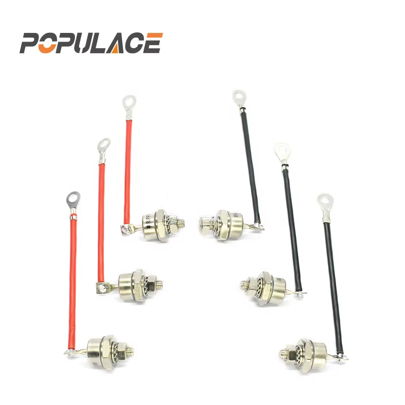
How to Source Diode Rectifiers for Generator Excitation Systems?
A failed excitation rectifier can look like an alternator problem, a regulator problem, or a wiring problem until the inspection gets specific. In a brushless generator, the exciter produces AC and the rotating rectifier converts it to DC for the main rotor field. That makes the Diode Rectifier a small but consequential part of voltage build-up and stable output.
As a technical consultant for generator control components, I would not source a replacement from a photograph or a generic amp rating alone. The practical question is whether the rectifier will match the exciter circuit, the rotating hardware, and the operating stresses of the particular alternator. This guide gives buyers a disciplined way to source a generator rectifier diode, a complete bridge, or a rotating assembly without turning a routine repair into a second failure.
Start by identifying the excitation arrangement
First confirm whether the machine uses a brushless rotating rectifier, a static excitation system, or another arrangement. A brushless unit normally has an exciter armature feeding a rotating diode bridge; its rectified output energizes the main rotor field. A static system may use a different rectifier layout altogether. A generic bridge rectifier for generator service is not automatically a substitute for a rotating assembly.
Ask the site team for the alternator nameplate, model, serial range, wiring diagram, and clear images of both sides of the existing assembly. Include the number of diode positions, lead or stud orientation, terminal markings, heat-sink arrangement, and any surge suppressors. Early in sourcing, buyers often focus on voltage and current labels. After an installation that will not fit or will not regulate, the attention shifts to polarity, mounting dimensions, and connector layout.
Build a specification sheet before requesting quotations
A useful request for quotation has enough detail for a supplier to verify compatibility rather than guess. Put these items in one sheet:
- Electrical duty: exciter phase arrangement, nominal field current where available, diode forward-current requirement, and required repetitive reverse-voltage or PIV margin.
- Rectifier configuration: number of positive and negative diodes, whether the request is for individual devices or a full rotating rectifier assembly, and the location of any varistor or surge-suppression parts.
- Mechanical interface: stud thread, body diameter, mounting centers, heat-sink thickness, clearances, and cable or busbar connection method.
- Polarity and marking: clear identification of anode/cathode orientation and part markings on the removed component.
- Application context: standby or prime-duty operation, ambient conditions, load behavior, and whether the generator experienced an overvoltage, short circuit, or rotor fault.
Current and voltage ratings deserve context. Rectifier diodes are selected with operating margin for current carrying and voltage withstand capability, not simply at the exact measured normal value. If motor loads cycle frequently, if a site sees transient events, or if the original design includes protection devices, verify that the replacement preserves the intended protection approach. The specification sheet is where an experienced supplier can flag a mismatch before production or shipment.
Choose between single diodes and a complete assembly
Replacing one generator rectifier diode can be appropriate when the rest of the bridge is verified, the matching part is available, and the heat sink is undamaged. It is not automatically the lowest-risk choice. A failed diode may be a symptom of a surge event, poor connection, overheating, or a fault elsewhere in the excitation circuit.
A complete rotating rectifier assembly can simplify mechanical matching and preserve the intended positive/negative layout. It may be a lower-risk route when several devices show abnormal readings, terminal hardware is heat damaged, or documentation for individual devices is weak. For either choice, ask what is included: diode devices, heat sinks, insulation hardware, suppressors, leads, and fastening parts are often quoted differently.
Check the AVR relationship without confusing the parts
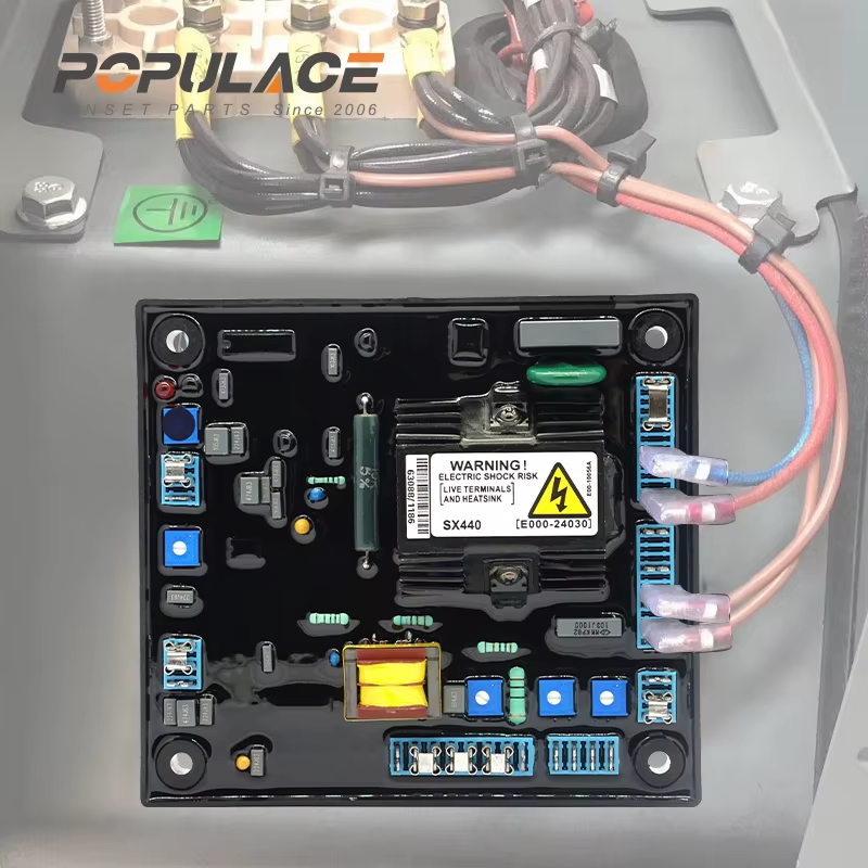
An avr rectifier module and a rotating rectifier do related electrical work in different parts of a system. The AVR controls excitation according to generator sensing and control logic; a brushless rotating bridge rectifies exciter output on the rotor. Do not substitute an AVR module for a rotating bridge or assume that an AVR fault confirms a bridge fault. Use the alternator schematic and the OEM troubleshooting sequence to identify which component is actually in circuit.
That distinction is especially important in a sourcing request. State whether you need a rotor-mounted diode bridge, loose diodes, or an AVR-related rectifier module, then attach the original part number if available. A supplier that performs pre-shipment compatibility review can help compare the evidence, but the final match should be anchored to the generator documentation and the removed component.
Screen suppliers on evidence, not only unit price
Price matters, particularly for distributors stocking repeat-demand parts. Still, the landed cost of a Diode Rectifier includes the cost of a return, a missed outage window, and the labor to remove a rotor again. Request drawings or dimensional confirmation, polarity confirmation, photos of markings, packing details, lead time, and a written statement of what the supplied configuration includes.
For a first order, consider a sample or a documented inspection gate before a larger purchase. Confirm that the supplier can identify the application from the model and original markings rather than promising universal compatibility. If you are comparing OEM and aftermarket options, the right choice depends on required traceability, availability, budget, and the level of technical documentation needed for the job; neither route is automatically best in every case.
Inspect and test the received parts before installation
Before fitting a bridge rectifier for generator duty, inspect the package and compare the received parts against the approved sheet. Check count, polarity marks, threads, dimensions, terminal orientation, and evidence of transit damage. With the generator safely isolated and procedures followed, diode-mode testing should show a clear difference between forward and reverse directions. A reading that is low in both directions can indicate a shorted device; no conduction in either direction may indicate an open device. Treat this as a screening step, not a replacement for the OEM service procedure.
Also examine the removed assembly for discolored insulation, loose connections, damaged surge devices, or uneven heat transfer surfaces. Replacing only the diode without addressing the cause can repeat the failure. Installation torque, insulation washers, routing, and balancing considerations should follow the alternator manufacturer’s instructions.
A practical sourcing checklist
- Identify the excitation topology and exact alternator model.
- Capture part markings, polarity, photos, dimensions, and the circuit diagram.
- Specify electrical ratings with suitable design margin and note surge protection.
- Decide whether a matched diode pair, a full bridge, or a rotating rectifier assembly most appropriately controls the identified risk.
- Require written compatibility confirmation and an itemized scope of supply.
- Inspect and electrically screen the received parts before installation.
- Commission according to the OEM procedure and retain the sourcing record for future service.
A sound sourcing result is not merely a diode that arrives quickly. It is a verified Diode Rectifier solution that matches the generator’s electrical and mechanical design, gives the maintenance team clear installation evidence, and reduces the chance of a repeat outage.






