
 EN
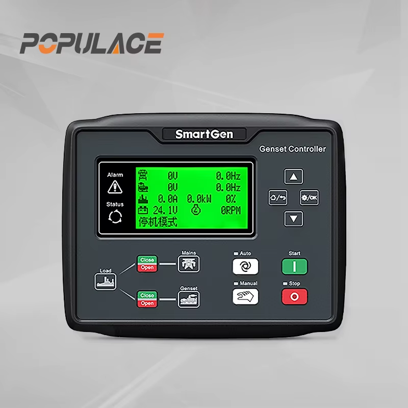
How to Set Up a Smartgen Controller for Dual Generator Mains Failure?
When a site has two standby generator sets and the utility supply fails, the goal is not simply to start both engines. A safe smartgen controller setup must define which generator starts first, how the second set is called, what feedback proves each breaker has moved, and when the load is allowed to transfer. The exact menu names and terminal assignments vary by model, so use the manual and wiring drawing for your controller before changing any parameter.
As a commissioning rule, treat the controller, the ATS or switchgear logic, and the generator protection system as one coordinated system. A smartgen generator controller can issue commands, but it cannot correct a missing electrical interlock, a wrongly landed auxiliary contact, or an unsafe breaker scheme.
Start with the operating sequence, not the programming screen
Write the desired sequence in plain language before opening the configuration software. For a common dual-generator mains-failure arrangement, the preferred set receives the first remote-start request after a verified mains-fail delay. The controller then waits for the engine to reach stable voltage and frequency, proves generator availability, and permits its breaker to close only when the downstream switching logic is ready. The second set is usually a reserve: it starts if the first set fails to become available, if an approved load-demand condition calls for it, or if the system design requires two sources.
- Define the normal source, preferred generator, reserve generator, and load bus.
- Specify what “mains failed” means: loss of all phases, undervoltage, underfrequency, or a combination approved for the site.
- Specify the acceptable delay before starting, transfer, retransfer, and cooldown.
- Decide whether both generators may run at once and, if so, whether they are isolated or designed for synchronizing and load sharing.
Do not use a dual-generator scheme as a substitute for approved protection and switchgear design. If generators can ever be paralleled, the application needs equipment and commissioning procedures intended for synchronizing, load sharing, and breaker protection.
Verify hardware and feedback signals first
Before smartgen controller programming, isolate the system according to the site’s lockout and safety procedure. Confirm DC supply polarity and fusing, emergency-stop circuit behavior, fuel and starter wiring, engine-running feedback, and the controller’s programmed input type. Then trace every status input used by the sequence: utility healthy/fail sensing, generator breaker closed, mains breaker closed, ATS position, remote start, and fault reset.
The most important practical check is feedback. A command output tells you what the smartgen controller requested; an auxiliary contact or monitored voltage tells it what actually happened. If a breaker-close output is configured without reliable breaker-position feedback, the logic can continue on a false assumption. Label every signal in the panel drawing and test it at the input screen before any automatic run.
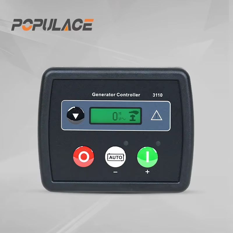
Set mains sensing and start logic
Configure the mains nominal voltage, phase arrangement, and qualification thresholds only from the approved site design and the applicable controller manual. Set a mains-failure delay long enough to reject brief disturbances but short enough for the facility’s backup-power requirement. Avoid copying values from another installation: a setting appropriate for one utility, load, or controller model may be wrong for another.
For the preferred set, enable the automatic start mode and assign its start condition to the verified mains-fail signal. For the reserve set, choose a defined escalation condition. Typical options include failure of the preferred generator to start, a generator-available timeout, a fault that blocks closing, or a demand signal from approved switchgear. The logic must prevent both units from repeatedly starting and stopping because of inconsistent feedback.
Configure generator availability before transfer
A smartgen controller should not declare a generator available merely because the engine is cranking or running. The sequence normally requires stable engine speed, generator voltage and frequency within the approved range, no active shutdown alarms, and any required warm-up timer complete. Configure these conditions in the relevant smartgen hgm series model manual rather than relying on generic assumptions.
Set the output function for each breaker or ATS command with care. Confirm whether the connected device expects a maintained output, a pulse, or a separate open and close command. Confirm the fail-safe state if controller power is lost. Test breaker commands with the power circuit disabled or in a controlled test arrangement first.
Plan the priority and fallback logic
Choose a clear priority policy. In a lead/standby design, Generator A is first choice and Generator B is called only when A cannot support the bus. In a rotating-duty design, priority alternates according to a documented maintenance policy. Either way, include a lockout or alarm path for a set that fails to start, fails to build voltage, or returns an invalid breaker status.
| Event | Expected control response | Commissioning proof |
|---|---|---|
| Verified mains failure | Start preferred generator after delay | Check timer and start output |
| Preferred set available | Permit planned transfer or breaker close | Check voltage, frequency, and feedback |
| Preferred set unavailable | Call reserve set and inhibit unsafe transfer | Simulate start or availability failure |
| Mains returns stable | Retransfer after delay, then cool down sets | Confirm no nuisance cycling |
Commission the system in stages
Start with individual controller I/O tests, then run each generator manually, then test automatic start without load transfer, and only then test controlled transfer with the responsible electrician and site operator present. Record the result of every test, alarm, timer, and feedback point. Restore normal settings after simulation tests.
When comparing a smartgen deep sea alternative, compare the required I/O, sensing, breaker control, communications, and support documentation—not brand names alone. Choose the controller and switchgear combination that matches the approved operating sequence and can be verified during commissioning.
Final checklist
- Controller model, firmware, and configuration file are recorded.
- Mains sensing and generator sensing match the wiring drawing.
- Preferred and reserve start conditions are documented.
- Breaker commands have independently tested position feedback.
- All shutdown, emergency-stop, and interlock functions are tested.
- Return-to-mains and cooldown behavior are witnessed under a controlled test.
Before handover, save the configuration file and record the active settings so the smartgen controller can be restored after service. During routine maintenance, test the smartgen controller with the approved generator test procedure, verify alarm history, and confirm that the smartgen controller still receives correct mains and breaker feedback. For complex installations, ask a qualified generator controls technician to review the sequence before energizing the live load. A disciplined setup turns a smartgen controller from a collection of parameters into a predictable response to mains failure.






