
 EN
How to Select a Three Phase Bridge Rectifier for High-Power Generator Applications?
A rectifier that looks adequate on a quotation can become the weak point in a generator auxiliary supply when load pulses, enclosure heat, or a wiring error arrive. As a technical consultant for generator control components, I start with the generator’s AC source, DC bus requirement, load profile, and cooling path—not with the largest current number printed on a catalog page. This guide explains how to select a three phase bridge rectifier for high-power generator work without treating nominal ratings as the whole story.
Start with the generator application, not the module package
A three phase bridge rectifier uses six diodes to convert three-phase AC into DC. In a generator system, it may feed a DC bus, battery charger stage, excitation-related auxiliary circuit, or industrial control load. Those applications do not impose the same electrical stress. Ask whether the generator is standby or prime power, whether the DC load is steady or cyclic, and whether motor starts, solenoids, contactors, or switching supplies create short peaks.
Early in a sourcing process, buyers often focus on voltage and current ratings. After a failed installation, the focus usually shifts to deeper compatibility factors: line voltage tolerance, surge exposure, heat removal, terminal arrangement, and the real DC current waveform. That is why a high power bridge rectifier should be selected as part of a system review rather than as an isolated replacement.
Calculate the voltage window before choosing a three phase diode bridge
Confirm the generator line-to-line RMS voltage at its expected operating range, then distinguish it from the rectifier’s DC output and its repetitive reverse-voltage requirement. For an ideal six-pulse bridge with continuous current, average DC output is commonly estimated at about 1.35 times the line-to-line RMS voltage. It is a useful first screen, not a promise of installed voltage: source impedance, commutation overlap, diode drops, ripple, and loading all change the result.
For example, a 400 V line-to-line supply suggests an ideal average near 540 V DC before losses. The reverse-voltage rating of each diode needs margin above normal peaks, including generator regulation changes and switching transients. Do not assume the average DC value is the maximum stress. If the input can be miswired, if long cables are present, or if inductive loads switch nearby, review transient protection and insulation coordination with the complete panel design.
- Record nominal, minimum, and maximum line-to-line voltage.
- Identify frequency and any overspeed or regulation excursions allowed by the generator system.
- Check the module’s repetitive peak reverse-voltage rating and its surge rating separately.
- Verify that downstream capacitors, fuses, contactors, and DC loads tolerate the resulting DC voltage.
Size current for continuous duty and short overloads
The next decision is not simply “choose a larger ampere rating.” Rectifier current ratings are tied to specified mounting and temperature conditions. A 3 phase bridge rectifier module operating in a warm generator canopy may deliver far less continuous current than the same part on a generous heatsink in a cool test environment. Read the datasheet conditions for average forward current, case temperature, thermal resistance, and permitted overload duration.
Build a load table that separates continuous DC current from expected peaks. Include capacitor charging inrush if a reservoir capacitor follows the bridge; that repetitive pulse current can be much higher than the average load current. Then review the diode’s non-repetitive surge-current capability against the protection scheme. A fuse or breaker must clear a fault in a manner compatible with the rectifier’s allowed energy, not merely protect the cable.
For a generator rectifier 3 phase application supplying electronics, a steady average current may look modest while charging pulses determine heating. For a magnetic or motor-related DC load, switching and start events may dominate. Whether a given margin is sufficient depends on the load waveform and ambient conditions; a catalog current number alone cannot answer that question.
Treat thermal design as a primary selection criterion
Every conducting path in a six-diode bridge produces loss. Two diodes conduct at a time, so forward-voltage loss becomes heat that must move from junction to case, through the interface material, into the heatsink, and finally into enclosure air. A rectifier with appropriate voltage and current ratings can still have a short service life if its mounting surface is uneven, thermal compound is poorly applied, airflow is blocked, or the generator room runs hotter than assumed.
Ask for the module’s thermal-resistance data and define the worst credible ambient temperature. Work backward from the permitted junction temperature using estimated conduction loss and the full thermal path. In practice, leave commissioning margin: measure case temperature under representative load after the enclosure doors are closed. If the application runs at a stable load profile, a calculated heatsink may be adequate. If load swings frequently or the generator operates in hot, dusty locations, test the temperature response through those cycles.
Check mechanical, wiring, and protection compatibility
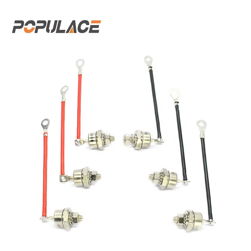
A three phase diode bridge may have the right electrical rating but the wrong mounting footprint, terminal torque requirement, creepage spacing, or polarity marking for the existing panel. Confirm the AC terminals, positive and negative DC terminals, mounting-hole pattern, isolation arrangement, and required heatsink flatness before placing an order. For replacement work, compare the original part number and drawing rather than relying on a similar-looking package.
Protection should be designed around the installation. Depending on the circuit, the review may include input fuses, semiconductor fuses, DC-side protection, surge suppression, snubbers, pre-charge arrangements, and a safe discharge path for DC capacitors. IEC 60146-1-1:2024 covers performance requirements for semiconductor power converters and semiconductor power switches; project teams should verify the applicable edition, local rules, and product documentation for their actual system. A standard reference is useful, but it does not replace a circuit-specific safety review.
Use a practical selection checklist
- Define the source: line-to-line voltage range, frequency, generator regulation behavior, and expected transients.
- Define the DC duty: average current, peak current, inrush, ripple tolerance, and load type.
- Set voltage margin: compare maximum credible AC and transient conditions with the rectifier’s reverse-voltage and surge limits.
- Set thermal margin: use the real ambient, heatsink, airflow, mounting method, and duty cycle.
- Verify interfaces: package outline, terminals, torque, insulation, clearances, and wiring layout.
- Coordinate protection: assess fuses, fault-clearing energy, surge control, and downstream capacitor behavior.
- Plan validation: inspect wiring, energize under controlled conditions, and log voltage and temperature at representative load.
Questions to send with an RFQ
Clear documentation avoids a surprising amount of rework. When requesting a three phase bridge rectifier, provide the AC line voltage range, frequency, target DC load, continuous and peak current, ambient temperature, heatsink details, enclosure constraints, desired package style, and any existing part number. Also ask for the current-rating test conditions, thermal curves, reverse-voltage rating, surge-current rating, mounting instructions, and outline drawing.
Experienced buyers often confirm compatibility before discussing price because an incorrect high power bridge rectifier can delay commissioning and create repeat labor. A supplier focused on generator control components may be able to support pre-order specification review and documentation checks; confirm the scope of that support for the exact module and application rather than assuming it applies to every configuration.
Conclusion
The right three phase bridge rectifier balances voltage margin, real current waveform, thermal path, mechanical fit, and protection coordination. Start with the generator’s actual operating envelope, then validate the module against worst-case—not just nominal—conditions. That approach makes a 3 phase bridge rectifier module selection more defensible for high-power generator applications and reduces the chance that an apparently suitable component becomes the next service call.






