
 EN
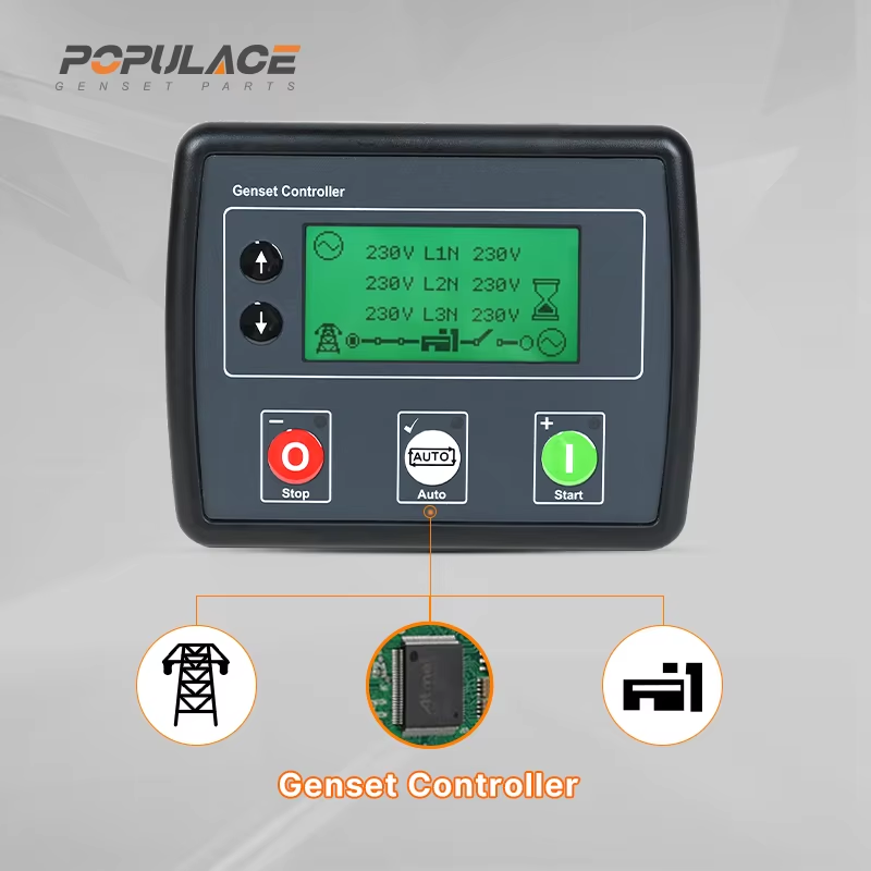
How to Program the DSE4510 for Automatic Transfer Switch Operation?
If you are looking at a DSE4510 for standby power, the first programming decision is also the most important: confirm what the controller is designed to do. The legacy DSE4510 is an auto-start generator controller. It can monitor a start request and manage a generator run sequence, but it is not an AMF/ATS controller that independently senses utility failure and commands a complete mains-to-generator transfer. That distinction prevents a lot of unsafe wiring assumptions.
As a genset maintenance engineer would put it, start with the operating sequence, not the menu. A correct sequence can use a DSE4510 as part of a larger transfer arrangement; a wrong sequence tries to make its auxiliary outputs behave like a dedicated ATS controller. Before changing settings, obtain the exact dse4510 controller manual for the controller variant and the approved schematic for the transfer panel.
Can a DSE4510 run an automatic transfer switch?
Not by itself. A DSE4510 is an auto-start module, whereas automatic transfer switching needs confirmed utility sensing, generator availability logic, electrically and mechanically interlocked switching, and the correct delay and retransfer behavior. For a new design, use a dedicated AMF/ATS controller or transfer-switch controller selected for that duty. The official replacement path for the obsolete DSE4510 points to an auto-mains-failure controller category, not to a simple reprogramming of the old module.
You may still find a DSE4510 in an existing panel where another device handles mains sensing and transfer logic. In that arrangement, the DSE4510 receives a dry start request, starts and protects the generator, then signals that the generator is available. The transfer equipment must remain responsible for contactor interlocking and load transfer. Do not use a controller output as a direct substitute for a contactor power circuit.
Build the operating sequence before opening the configuration software
Write down the sequence your panel must follow. This short exercise exposes missing signals before any parameter is changed:
- Utility supply is normal; the generator is stopped and the load remains on the utility source.
- The transfer panel detects a confirmed utility failure and waits through its configured fail delay.
- The panel sends a start request to the DSE4510. The controller performs its configured crank, rest, and start sequence.
- After the generator reaches acceptable voltage and frequency according to the approved settings, the transfer panel may transfer the load using its interlocked switching hardware.
- When utility is stable again, the transfer panel retransfers the load, removes the start request after its cooldown logic, and the DSE4510 completes its stop sequence.
The exact timing values are site-specific. A hospital, pump station, and warehouse may require different delays and testing procedures. Do not copy a value from a dse 4510 wiring diagram unless the diagram matches the controller version, engine interface, transfer equipment, and local electrical design.
Safe DSE4510 programming workflow
1. Identify the controller and save the existing configuration
Read the product label and firmware information first. Do not mix legacy DSE4510 instructions with DSE4510 MKII or DSE4520 MKII documentation; menu names and capabilities can differ. With authorized configuration software and a stable service connection, save the existing file before editing. Record the engine type, start method, battery voltage, input assignments, and output assignments. That backup is your fastest recovery path if a test reveals an incorrect setting.
2. Verify the start input assignment
For an existing transfer installation, identify which terminal input receives the remote start signal and whether the signal is maintained, momentary, positive, or negative switching. Configure only the function documented for that input. Then test the start request with the load isolated and an operator present. The DSE4510 should start only when the designated request is active and should report any failed-start or safety shutdown condition clearly.
3. Review generator protection settings with qualified personnel
Set and verify voltage, frequency, oil-pressure, temperature, and speed-related protection only against the engine and alternator documentation. A controller setting that is too wide can allow poor-quality generator power; one that is too tight can create nuisance shutdowns. This is why the dse4510 controller manual belongs beside the generator and engine specifications during commissioning, not just in a purchasing file.
4. Configure outputs as status signals, not as power switching circuits
Use configurable outputs for documented functions such as generator available, common alarm, or remote status where the panel design calls for them. Confirm the output type, polarity, load rating, and any required interposing relay. The DSE4510’s auxiliary outputs are control signals; they are not evidence that the module can safely energize a transfer contactor coil or replace mechanical and electrical interlocking. A qualified panel builder should review the entire control circuit.
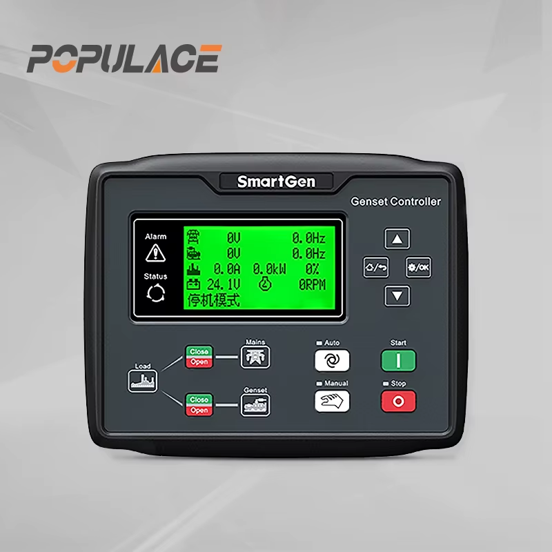
How to read a DSE 4510 wiring diagram without making a transfer error
A reliable drawing separates three layers: controller I/O, engine interface, and transfer-switch power/control circuits. Trace each signal from source to destination. For example, the ATS or AMF device may send a remote-start contact to the controller; the controller may return a generator-available status; and the ATS uses its own logic to move the load. If the drawing does not show those responsibilities separately, stop and obtain the correct panel schematic.
- Check the DC supply polarity, fuse protection, and battery disconnect procedure.
- Confirm every input’s source and normal state before connecting it.
- Check that utility and generator contactors are interlocked by the approved panel design.
- Verify emergency-stop and shutdown circuits independently of normal automatic signals.
- Label test points so the next technician can distinguish a start request from a transfer command.
Commission with staged tests, not one live transfer
After configuration, test in stages. First verify indication and alarms without a start request. Next test a manual or controlled remote start with the load isolated. Then confirm generator voltage and frequency acceptance. Only after the transfer equipment has been separately inspected should you perform a supervised automatic sequence. Capture start delay, warm-up, transfer, retransfer, cooldown, and shutdown behavior in a commissioning record. If any step differs from the approved sequence, return to the drawing and configuration backup rather than adjusting several settings at once.
What about deep sea 4510 amf upgrades and dse4510 price?
Searches for deep sea 4510 amf often reflect a need for utility-failure operation, but the controller category matters more than the label. A retrofit may require a dedicated AMF controller, an ATS controller, revised wiring, and a new commissioning test. When comparing dse4510 price with a replacement option, include the cost of documentation, compatibility review, panel modifications, and safe commissioning. A lower module price does not reduce the risk of using the wrong control architecture.
Final checklist
Program a DSE4510 only after you have confirmed that it is being used as an auto-start controller within a properly designed system. Keep the controller manual, the exact panel schematic, and the engine/alternator data together. Confirm which device senses mains, which device commands transfer, and which output proves generator availability. If those answers are unclear, pause the work and have a qualified generator-control or switchgear professional review the design before energizing the ATS.






