
 EN

How to Program a DSE Controller for Automatic Start and Stop?
Programming a dse controller for automatic start and stop is not mainly a matter of finding one menu item. It is a commissioning task that links the controller configuration, engine interface, breaker or ATS logic, and the site’s operating rules. A wrong setting can cause nuisance starts, a generator that will not release the load, or an unsafe stop sequence. The most reliable approach is to confirm the wiring and intended operating sequence first, then configure and test one function at a time.
This guide applies to common manual-start and AMF-style DSE genset controller applications. Exact labels, available inputs, and configuration paths differ by firmware and model, so use the current manual and configuration software documentation for the installed module.
Start with the operating sequence, not the software
Before connecting a laptop, write down what should make the generator run and what should make it stop. A typical automatic sequence is: a remote-start contact closes, or utility supply fails; the controller waits through a start delay; the engine cranks and reaches healthy speed and voltage; the generator is allowed to take load when the transfer logic permits it. When the request disappears or utility returns, the controller removes the generator from load, runs an unloaded cooldown, then stops the engine.
A dse genset controller can be used in several arrangements. A remote-start-only system reacts to an external dry contact. An AMF system also uses mains sensing and changeover outputs. Scheduled runs may be added for exercise purposes. These arrangements share a basic start-and-stop concept, but their safety checks and load-transfer settings are not interchangeable. Before activating Auto on a dse controller, confirm whether the request is meant to start off load, start on load, or initiate a mains-failure transfer.
Pre-programming checks that prevent false starts
- Identify the exact module and firmware. A DSE 7320 controller and a DSE 6020 controller are different product families with different I/O capability and menu structure.
- Confirm the engine interface. Verify fuel, starter, preheat, speed sensing, oil pressure, temperature, emergency-stop, and ECU connections against the engine and controller drawings.
- Check input polarity and contact type. A remote-start input configured for a negative signal will not behave correctly if the site contact supplies a positive signal, and vice versa.
- Confirm the load path. Determine whether the controller only starts the set, operates a generator breaker, controls an ATS, or manages a mains-failure transfer sequence.
- Make the test safe. Isolate or simulate the start request where possible, notify affected staff, and ensure the emergency stop is functional before attempting an automatic test.
Do not use a live utility failure as the first test. A simulated input or supervised test arrangement makes it easier to distinguish a wiring fault from a setting problem.
Program the automatic start source
In the configuration software, assign a suitable digital input to the real start source. For a basic remote-start application, this is commonly an input function such as remote start, start on load, or start off load. The label matters: a start-on-load request can be intended to start the engine and enable load transfer, while a start-off-load request may exercise the set without connecting it to the site load.
For AMF operation, configure the mains-voltage sensing and the start-on-mains-failure logic for the actual supply arrangement. Verify phase configuration, nominal voltage, frequency, and the acceptable under-voltage, over-voltage, under-frequency, and over-frequency limits. These values must come from the site design and equipment ratings, not from a generic example. A dse controller should see stable, correctly phased sensing before it is asked to make automatic transfer decisions.
Set a deliberate start delay. The delay filters brief contact bounce or short mains disturbances so the generator is not started for every transient. In critical applications, coordinate this delay with the ATS and facility operating plan.
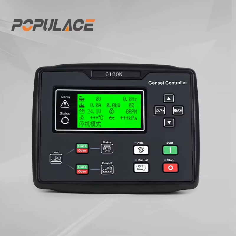
Set the engine start and protection sequence
The dse controller needs a complete engine-start profile: preheat if required, crank time, rest time between crank attempts, the number of attempts, and the condition that proves the engine is running. Run detection may use oil pressure, magnetic pickup speed, alternator frequency, ECU data, or a combination specified for the engine. Do not disable start protections merely to make a test pass; correct the sensing or wiring issue instead. In every dse controller setup, document which signal ends cranking and which signal confirms that the engine may proceed to its warm-up or load-ready stage.
Review the safety inputs before enabling Auto. Emergency stop, low oil pressure, high coolant temperature, overspeed, fail to start, and fail to stop must be assigned and tested in accordance with the approved commissioning procedure. Some alarms are intentionally inhibited during cranking and warm-up. The correct timers depend on the engine manufacturer’s requirements.
Configure load transfer and automatic stopping
Automatic stopping begins with a clean unload. In an AMF application, confirm that the generator breaker or ATS output opens before fuel is removed. In a remote-start-only application, confirm whether the controller should only run the engine or also command a breaker. Incorrect output assignment is a common reason a set runs correctly but transfers incorrectly. Review the dse controller output status during the test rather than assuming that a healthy engine signal proves a safe transfer sequence.
Next, set the return-to-mains or stop delay and the cooldown timer. The stop delay prevents rapid cycling when the start request flickers. The cooldown timer lets the engine run without load after transfer has completed, helping manage heat before shutdown. It is not a universal fixed value: use the engine, enclosure, load profile, and site procedure to establish the appropriate setting. This is one reason a dse controller configuration should be reviewed as a complete sequence rather than as unrelated timer values.
On many DSE modules, Auto mode is the operating state that accepts automatic requests. Manual and test modes are useful for commissioning, but they are not proof that automatic operation is configured. For example, operator-manual material for the DSE 7320 family describes Auto mode as monitoring start requests and beginning a stopping sequence after requests are removed. Treat this as a behavior check, not as a substitute for the installed model’s manual.
Commission in a controlled order
- Save a dated backup of the existing configuration before changing parameters.
- With the generator safe and unloaded, verify each digital input’s live status in the software or display.
- Test manual start and stop first, including run indication and alarm response.
- Place the module in Auto and apply a simulated start request. Check start delay, cranking, run detection, and any required warm-up.
- Where approved, verify breaker or ATS sequencing under supervision.
- Remove the request and confirm unload, stop delay, cooldown, and final engine stop.
- Record the configuration revision, signal logic, timer values, test results, and unresolved observations.
Notes for DSE 7320 and DSE 6020 applications
A dse 7320 controller is often used where generator and mains monitoring, AMF functions, or broader I/O are required. A dse 6020 controller may be used in a different operating scope. Do not copy a configuration file between models unless the manufacturer documentation confirms compatibility and every input, output, sensing connection, and protection setting has been reviewed. A settings file can look valid while commanding the wrong terminal behavior. The dse controller name on the fascia is not enough: verify the complete model code, module generation, and controlled application.
When sourcing replacement control components or requesting technical assistance from a deep sea electronics distributor, provide the full controller model, engine model, system voltage, control philosophy, wiring drawing revision, and the required start source. Those details are more useful than a photo of the front panel alone.
Final checklist
A successful automatic test should show the correct trigger, one controlled start sequence, healthy engine confirmation, correct load behavior where applicable, stable operation, controlled unload, cooldown, and stop. If the set starts repeatedly, refuses to stop, or transfers unexpectedly, return to the signal logic and output assignments before changing timing values. Methodical verification is the safest way to program a dse controller for dependable automatic operation.





