
 EN
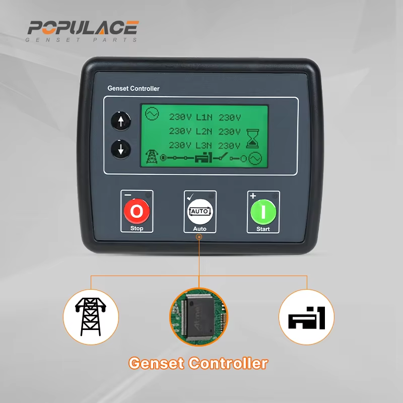
How to Integrate the DSE704 into a Complex Generator Control System?
Adding a DSE704 to a multi-device generator control system is not simply a matter of landing wires on the nearest terminals. The controller sits at the point where engine signals, generator sensing, utility sensing, breaker logic, safety circuits, and remote commands meet. A sound integration therefore starts with the operating sequence, then turns that sequence into verified inputs, outputs, interlocks, and test points.
The DSE704 is commonly used as an auto-mains-failure controller: it monitors the supply, starts a generator when the required conditions are met, and participates in returning the installation to normal operation. In a complex panel, it must work with equipment such as a transfer switch, breaker auxiliaries, battery charger, emergency-stop loop, fire interface, remote annunciation, and sometimes a supervisory PLC. The exact terminal functions and limits should be confirmed against the correct revision of the dse704 manual; this article explains the integration method rather than substituting for that document.
1. Define the control boundary before wiring the DSE704
Begin with a one-line diagram and a written sequence of operation. State who owns each decision: the DSE704 controller, an automatic transfer switch (ATS), a breaker controller, or a site PLC. Conflicting ownership is a common cause of nuisance trips and unsafe switching. For example, decide whether the DSE704 sends only a start request and observes breaker feedback, or whether it is the device that commands generator and mains contactors.
Map the signals in four groups:
- Measurements: generator voltage/frequency and utility voltage, using the sensing arrangement specified for the installation.
- Engine protection: oil pressure, coolant temperature, overspeed or other permitted inputs, with a clear definition of normally open versus normally closed contacts.
- Commands: fuel/run, crank, preheat if used, generator close, mains close, and any remote start or inhibit command.
- Feedbacks: generator available, breaker open/closed status, charger alarm, emergency stop, and lockout status.
Do not assume similarly named contacts are interchangeable. A controller may issue a close command, but it needs trustworthy auxiliary feedback to know whether a breaker actually changed state. This is one place where a documented compatibility review is more valuable than a fast wiring job.
2. Separate power wiring from control wiring
Route mains and generator sensing conductors, DC control conductors, and high-noise loads with deliberate separation. Label both ends of every core and maintain a terminal schedule. The DSE704 should receive its DC supply through correctly selected protection and an emergency-stop arrangement that follows the panel design. Keep starter and fuel-actuator circuits from back-feeding low-level inputs through shared commons or incorrect relay wiring.
For the power path, use mechanically and electrically interlocked switching equipment that is appropriate for the system. The controller logic is not a replacement for a rated changeover assembly. Before energizing, confirm the intended break-before-make or other approved transfer behavior, phase identification, neutral treatment, earthing arrangement, and protective-device coordination with the responsible electrical engineer.
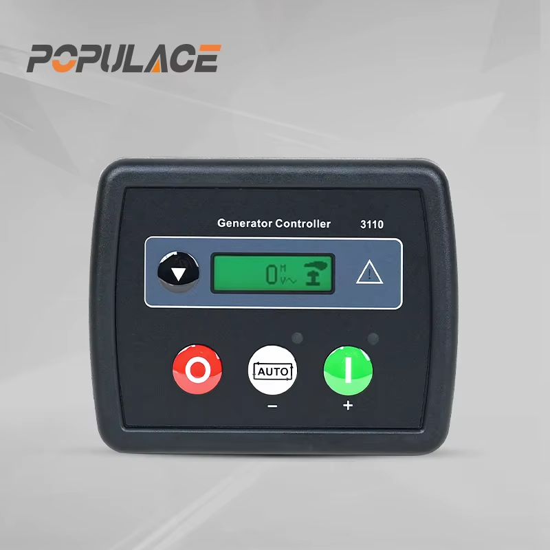
3. Build a signal matrix for the DSE704 controller
A signal matrix turns a difficult installation into a reviewable one. For every I/O point, record source device, contact state in normal operation, state on fault, cable number, terminal, and what the DSE704 should do when the signal is lost. Include timing assumptions. A low oil pressure input, for instance, may need to be ignored during cranking and enabled only after the engine has had time to build pressure.
| Function | Question to settle | Commissioning evidence |
|---|---|---|
| Remote start | Is it maintained, momentary, or supplied by a PLC? | Prove start, stop, and loss-of-signal behavior. |
| Mains failure | What voltage/frequency condition and delay constitute failure? | Record simulated loss and restoration tests. |
| Breaker feedback | Which auxiliary contact confirms each breaker position? | Verify feedback matches the physical position. |
| Safety chain | Which devices can inhibit cranking or force shutdown? | Test each device individually with documented reset rules. |
This approach also prevents a subtle integration error: treating the DSE704 output relay as a power-switching device. Use appropriately rated interposing relays or contactors where the load, voltage, or fault duty requires them.
4. Configure in stages, not all at once
Use dse704 software only after the panel wiring has been checked against the approved drawings. First establish basic engine start/stop behavior without automatic load transfer. Then validate generator measurement and protection. Next prove utility sensing. Finally enable close commands and automatic transfer under controlled conditions. Saving a configuration file is useful, but it is not proof that the connected hardware behaves as intended.
Set delays and thresholds from the generator, transfer equipment, and site requirements—not from a generic template. If the generator carries motor loads or a sensitive process, the acceptable recovery sequence may differ from a simple standby set. Likewise, an external PLC should exchange only well-defined commands and statuses; avoid parallel control paths that let both systems try to close the same breaker.
5. Commission with a written test sequence
Before automatic operation, carry out a controlled functional test with competent personnel, isolation procedures, and the manufacturer documentation available. A practical sequence is:
- Inspect polarity, fusing, terminal tightness, shielding, labels, and protective earth connections.
- Prove emergency stop, start inhibit, and each shutdown input with outputs made safe.
- Run the engine locally and confirm that generator voltage and frequency readings are credible.
- Simulate utility failure and verify start delay, warm-up, generator-ready logic, and transfer permissives.
- Verify breaker commands and independent open/closed feedback; do not rely on relay indication alone.
- Restore utility, observe retransfer and cooldown, then review alarms and event records.
Keep the as-built drawings, configuration backup, test results, and revision of the deep sea 704 documentation together. If a future technician changes a timer or replaces a relay, that record makes the difference between a controlled maintenance task and a risky guess.
Common integration mistakes to avoid
The most frequent problems are mismatched contact logic, missing breaker feedback, undefined PLC ownership, and configuration changes made without a recorded baseline. Connector wear and loose terminals can mimic a software fault, so inspect physical connections before changing parameters. And while an older dse704 manual may be helpful for background, confirm that its terminal designations and configuration steps match the controller revision in the panel.
Final checklist
A reliable DSE704 integration comes from disciplined boundaries: one agreed sequence of operation, one signal matrix, correctly rated switching hardware, staged configuration, and witnessed tests. When the system is complex, involve qualified generator and electrical-control professionals early. They can validate protective functions and transfer interlocks before the controller is allowed to operate the installation automatically.
DSE704 integration questions technicians ask
Can a DSE704 controller work with a site PLC?
Yes, a DSE704 controller can be part of a PLC-supervised design when the command ownership is explicit. Let the PLC issue a defined remote request and let the DSE704 controller return defined run, alarm, and ready statuses. Avoid using a PLC output to duplicate a DSE704 controller breaker command unless the approved sequence expressly calls for it.
What should be checked before changing DSE704 software settings?
Back up the active dse704 software configuration, note its revision, and compare every changed setting with the cause-and-effect chart. DSE704 software settings for start delays, sensing, and protection must match the connected panel—not a configuration copied from another generator.
Which document controls the wiring decision?
The current dse704 manual for the installed controller revision is the authority for terminal details. A deep sea 704 panel can have additional relays, interlocks, and field wiring that are not shown in a basic example, so the dse704 manual must be read alongside the approved panel drawings. If the deep sea 704 system has been modified, update the drawings before recommissioning.






