
 EN
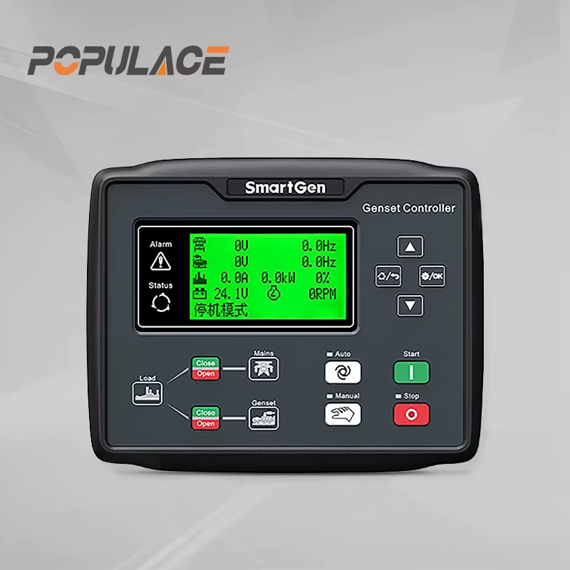
How to Import Generator Control Module Units for Genset Panel Integration?
Importing a generator control module is not a matter of choosing a screen size and landing it in a panel. The module has to agree with the engine interface, alternator sensing arrangement, DC supply, protection philosophy, and the way the finished genset will be commissioned. A controller that powers up but has the wrong inputs, outputs, or voltage assumptions can turn a routine panel build into an extended fault-finding job.
For wholesalers and panel builders, the most useful starting point is compatibility rather than brand preference. A practical review asks: what must this generator control module read, what must it command, and what is allowed to stop the set? The answers belong in the purchase specification before an import order is released.
Start by defining the genset application
Write down the operating mode first. A manual-start set, an automatic mains failure set, a parallel-capable set, and a mobile unit can all use a generator control board, but their I/O and protection requirements are different. Also identify the engine family, governor type, starter circuit voltage, fuel solenoid logic, alternator voltage, phase arrangement, frequency, and whether current transformers will be fitted.
Supply voltage deserves an early check. Generator control modules are commonly offered for different DC control supplies, such as 12 V or 24 V, and some designs cover a wider range. Do not assume that a module that fits the panel cutout will tolerate the site battery system. Confirm the permitted operating range, negative or positive switching arrangement, and the protection required for the DC feed.
Build a compatibility sheet before you import
A one-page compatibility sheet keeps purchasing, panel wiring, and commissioning aligned. Ask the supplier to confirm each point against the exact part number and revision, rather than relying on a generic catalog image.
| Interface | What to confirm | Why it matters |
|---|---|---|
| DC power | Nominal voltage, operating range, fuse recommendation, and grounding method | Prevents undervoltage resets and damage during cranking |
| Alternator sensing | Single- or three-phase sensing, terminal references, and voltage range | Ensures displayed and protected voltage matches the alternator connection |
| Current measurement | CT secondary rating, number of CT inputs, and phase assignment | Supports load display and overcurrent protection logic |
| Engine signals | Oil pressure, coolant temperature, speed pickup, fuel, and start/stop signal types | Avoids mixing analog, switch, and frequency inputs |
| Outputs | Relay ratings and normally open/normally closed logic | Confirms the module can drive intermediate relays safely |
| Communications | Protocol, port type, address settings, and monitoring purpose | Prevents a mismatch with the site monitoring system |
The same discipline applies when a buyer refers to a digital control module genset solution. “Digital” describes the control approach; it does not establish that the sensing terminals, output logic, or engine protocol are compatible with a particular panel.
Separate a genset controller from a generator ECU
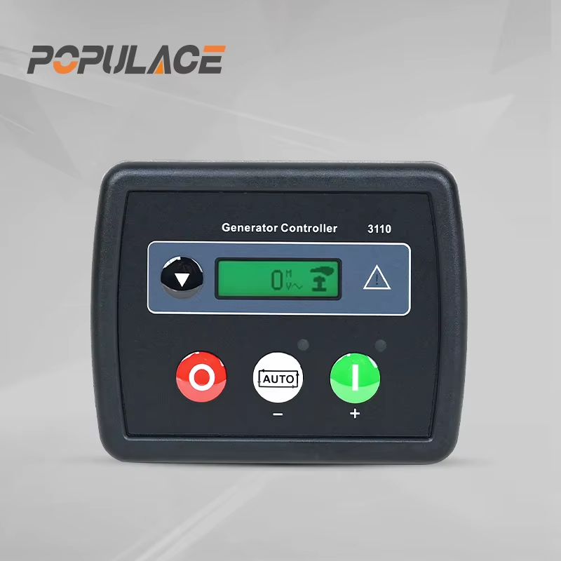
Search results often mix stationary-generator products with automotive parts. A generator ECU may be part of an engine or vehicle electrical architecture, while a genset controller is normally selected to supervise start/stop, generator measurements, alarms, and shutdown actions in a dedicated power-generation panel. They can exchange signals in some installations, but they should not be treated as interchangeable.
Before importing, request a terminal diagram and identify every connection that crosses the engine-panel boundary. Pay special attention to the run signal, crank signal, emergency-stop chain, magnetic pickup or speed source, charge alternator input, and any CAN communication. If the engine uses an ECU, establish which functions remain controlled by the ECU and which alarms the panel must receive. That division is project-specific.
Plan the panel wiring around signal quality and serviceability
A reliable control module for generator use is only as good as the installation around it. Route low-level sensing and communication wiring away from high-current starter, charger, and AC power conductors where the panel design allows. Use the correct terminal identification, conductor size, shielding practice, fusing, and earth arrangement specified for the actual module. Label both ends of every field conductor so a technician can trace the signal during startup or future service.
For CT circuits, confirm the phase order and maintain a safe, documented approach to secondary handling. For voltage sensing, verify that protective devices and terminal links match the drawing. A small terminal-map error can make a healthy alternator look like a controller fault. Experienced panel teams therefore test each input at the terminal strip before blaming the generator control module.
Use a staged commissioning sequence
- Inspect with power off. Compare the installed module, wiring labels, fuses, and terminal numbers with the approved diagram.
- Power the DC circuit. Check module startup, battery voltage reading, alarm state, and emergency-stop behavior before attempting a crank.
- Verify engine I/O. Confirm start, stop, fuel, speed, and analogue or switch inputs one at a time. Use safe simulation methods where appropriate.
- Verify AC sensing. With the set running, validate phase sequence, voltage, frequency, and current readings against suitable test instruments.
- Test protections and operating modes. Test only under an approved commissioning plan, including warning, shutdown, manual, and automatic sequences relevant to the project.
- Record the final configuration. Save settings, firmware or configuration revision, terminal map, and test results with the panel documentation.
If your application operates at a stable load, basic monitoring may be straightforward. If it sees motor starts, variable loads, remote monitoring, or automatic transfer functions, verify the settings and external relays against those conditions instead of relying on a default configuration.
What to include in the import package
Ask for the exact model number, revision, user manual, installation drawing, wiring or terminal schedule, configuration guide, packing list, country-of-origin documentation where required, and a clear warranty process. For repeat purchasing, retain a first-article sample record with photos of labels and connector layouts. This makes it easier to control revisions when the next shipment arrives.
Price still matters, but a higher-priced generator control board is not automatically a better fit. The decisive factor is whether the importer can verify the inputs, outputs, sensing method, and service documentation needed for the intended genset. That neutral approach reduces rework and helps a panel builder source a generator control module that can be integrated, tested, and supported with confidence.
Final checklist
- Match DC supply, engine signals, alternator sensing, and CT inputs.
- Confirm relay logic and ratings before connecting external loads.
- Keep automotive generator ECU terminology separate from genset-panel requirements.
- Use the approved drawing for wiring and commissioning, not a generic online diagram.
- Keep the model, configuration, and test record with the finished panel.
With those checks complete, importing a generator control module becomes a controlled integration task rather than a guessing exercise.






