
 EN
How to Connect an AVR GAVR 12A to a Three-Phase Alternator
Connecting an avr gavr 12a to a three-phase alternator is not a “match wire colors and start the set” job. The regulator must see the correct alternator voltage and send field current to the correct winding with the correct polarity. A wrong connection can produce no build-up, runaway voltage, unstable output, or damage to the AVR and rotating exciter. Treat the alternator terminal diagram and the exact GAVR-12A label as the final authority; terminal names and ratings can differ between revisions and generator designs.
As a maintenance workflow, begin by separating identification from adjustment. First map the terminals. Then make the low-risk connections with the engine stopped. Only after a controlled start should you set voltage, stability, and under-frequency behavior. This approach is more reliable than copying a generic avr gavr 12a wiring sketch from another alternator.
What the GAVR-12A does in a three-phase alternator
A gavr-12a voltage regulator compares the alternator’s sensed AC voltage with its internal reference. When output voltage is below target, it raises DC excitation to the exciter field; when voltage is high, it reduces excitation. The main rotor then changes the magnetic field seen by the stator, bringing generator output back toward the selected voltage.
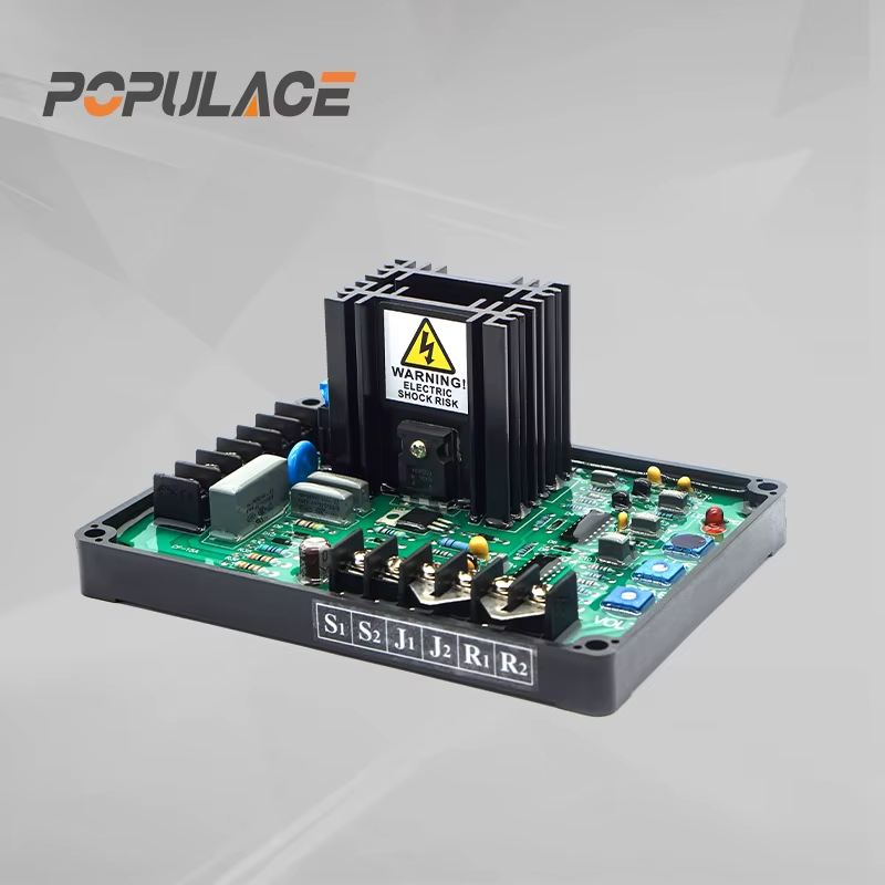
That feedback loop has two separate circuits. The sensing circuit measures alternator output. The field-output circuit feeds the exciter field. They must not be treated as interchangeable without confirmation. On many installations, the sensing leads are connected across the specified alternator output terminals, while the two field leads run to F+ and F− or similarly marked field terminals. Read the stamping on the regulator and the alternator wiring diagram before deciding which physical studs correspond to those functions.
Safety and information to collect before wiring
Lock out the genset, prevent automatic start, disconnect the battery starting supply where site procedures require it, and verify that all terminals are dead. Use an insulated meter rated for the expected generator voltage. If the set has been running, allow the AVR and alternator compartment to cool before handling conductors.
- Record the alternator model, rated line-to-line voltage, frequency, and connection type.
- Photograph the existing wiring and label every removed lead.
- Find the alternator drawing that identifies voltage-sensing points and exciter field leads.
- Check the GAVR-12A terminal markings, input-voltage range, and frequency setting on the actual unit.
- Inspect field leads, plugs, and ring terminals for heat discoloration, loose crimps, or connector wear.
This last check matters. What looks like an AVR fault is sometimes a high-resistance field connector or a damaged sensing lead. A universal 12A AVR can regulate only the voltage it actually receives and the field circuit it can actually drive.
Identify the four connection functions
1. Voltage-sensing inputs
The sensing pair, often labeled with AC, voltage, or input markings, connects to the alternator output points specified by the regulator documentation. For a three-phase machine, do not automatically connect across any two phase terminals. The required sensing arrangement depends on the AVR version and the alternator’s rated voltage. Confirm whether the documentation calls for phase-to-phase sensing, phase-to-neutral sensing, or an auxiliary winding connection.
2. Field-excitation outputs
The field-output pair, often identified as F+ and F−, connects to the exciter field terminals designated by the alternator maker. Preserve polarity. Reversing field leads can prevent voltage build-up or create abnormal regulation behavior. If the alternator diagram uses names such as X, XX, E+, or E−, establish the mapping from that drawing rather than guessing from lead colors.
3. Optional remote voltage trim
Some regulator versions support a remote voltage adjuster. If your unit has those terminals and the original system used a trim potentiometer, wire only the specified value and connection method from the manual. Leave optional terminals unconnected when no approved accessory is fitted; improvised jumpers can cause unstable regulation.
4. Frequency or droop-related connections
GAVR-12A documentation commonly identifies a U/F control for under-frequency protection. Some generator systems also have droop or parallel-operation hardware. Those features are application-specific. A standalone set should not be wired as though it were a paralleled machine, and a paralleled set needs its approved control design rather than a generic regulator-only connection.
Step-by-step avr gavr 12a wiring procedure
- Verify the alternator state. Confirm the stator, exciter field, and sensing leads with continuity checks against the alternator drawing. Do not use continuity alone to identify live phase relationships.
- Set controls conservatively. Before startup, place the VOLTS control near its documented initial position. Set STAB to a middle position if the manufacturer gives no different commissioning value. Do not turn adjustment pots fully clockwise.
- Connect the sensing leads. With the engine stopped, land the two sensing conductors on the exact alternator points prescribed for the regulator’s rated input. Route them away from ignition and high-current cables where practical.
- Connect the field leads. Connect F+ to the confirmed positive exciter-field terminal and F− to the confirmed negative terminal. Tighten hardware to the alternator manufacturer’s torque guidance and protect exposed connections.
- Recheck isolation. Verify that sensing wiring is not shorted to the field circuit, chassis, or an unintended phase. Check that no loose wire can touch rotating or hot components.
- Start without sensitive load. Run the engine at rated speed and observe output voltage and frequency using calibrated instruments. Keep loads disconnected until the voltage response is stable.
- Adjust voltage slowly. Turn VOLTS in small increments and wait for the output to settle after each move. The aim is the alternator’s specified no-load voltage, not a value copied from another generator.
- Set stability. If voltage hunts or oscillates, make small STAB adjustments, allowing time between changes. If it will not stabilize, stop and inspect engine speed governing, field wiring, sensing integrity, and the alternator itself.
- Check U/F behavior. Confirm the generator runs at rated frequency before judging voltage regulation. Under-frequency protection intentionally reduces excitation when speed falls, so a low-voltage reading at low RPM is not automatically a failed 12 amp generator avr.
Commissioning checks under load
After no-load voltage is stable, apply load in steps appropriate to the genset rating. Record line voltage, frequency, and field behavior at each step. Look for voltage drift, severe dip, repeated oscillation, overheating, or an AVR that cannot reach target voltage. A stable reading at no load but poor behavior under load can point to incorrect sensing, an engine-speed issue, a weak exciter system, or a load beyond the generator’s capability.
For service teams and distributors, keep the final terminal map, control settings, and measured readings with the set records. That documentation speeds replacement-AVR work and helps distinguish a compatibility issue from an installation issue. Fujian Kaiyue Electronics Co., Ltd. focuses on generator control components and replacement parts, but compatibility still depends on the actual alternator circuit, not a model name alone.
Common mistakes to avoid
- Using a generic wiring diagram without matching it to the regulator revision and alternator terminals.
- Connecting sensing leads to an incorrect voltage point for a three-phase configuration.
- Reversing field polarity or relying only on wire color.
- Adjusting VOLTS to compensate for low engine speed instead of correcting the governor or engine RPM.
- Making large, rapid STAB adjustments and mistaking the resulting oscillation for an AVR defect.
- Replacing the regulator before checking terminal tightness, exciter resistance, and sensing continuity.
Final takeaway
The safe way to connect an avr gavr 12a is to map sensing and field functions from the exact alternator and regulator documentation, wire with the set isolated, and commission at rated speed with no load before applying load. The GAVR-12A controls labeled VOLTS, STAB, and U/F are useful only after the terminal mapping is correct. When a label, wiring diagram, or measured result conflicts with a generic guide, stop and follow the equipment-specific documentation or consult a qualified generator technician.






