
 EN
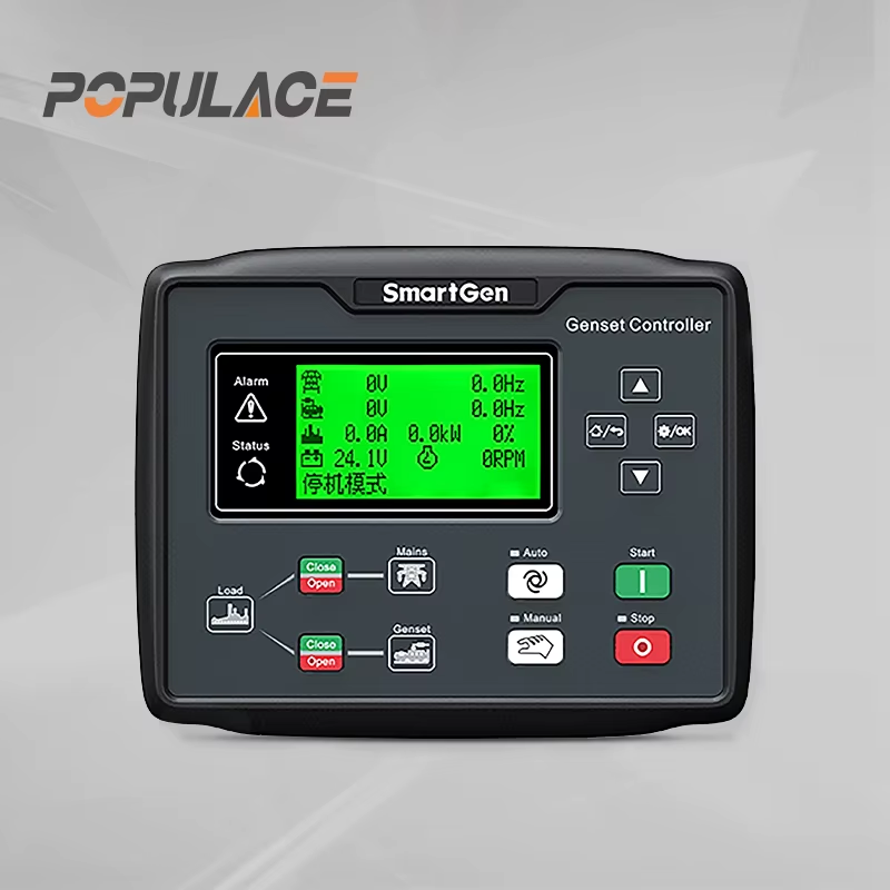
How to Calibrate a Governor Genset for Optimal Performance?
A governor genset calibration is not a quick “turn it until it sounds right” job. The governor is part of the engine fuel-control loop, so a small change can alter speed recovery, frequency stability, load sharing, and overspeed margin. A safe result starts with the correct manual, a stable mechanical system, and a documented test plan—not with a live adjustment on an unknown controller.
From a maintenance-engineer viewpoint, first confirm whether the governor for diesel genset is the original specification or an approved replacement. Connector wiring, actuator travel, speed pickup signal, controller firmware, and operating mode all affect the final setting. If any of those are uncertain, stop and obtain the engine and generator-set documentation before changing parameters.
Start with safety and the right baseline
Only a qualified technician should adjust a running set. Follow the site lockout, emergency-stop, guarding, ventilation, hearing protection, and arc-flash procedures. Keep a second person available where local practice requires it. Do not defeat overspeed, low-oil-pressure, high-temperature, or electrical protection to make a calibration easier.
- Record the genset model, engine model, governor controller model, actuator part number, rated voltage, rated frequency, pole count, and operating mode.
- Capture existing controller settings and event logs before editing anything. If the controller supports a configuration export, save it with the job record.
- Inspect fuel linkage, return springs, actuator mounting, speed-sensor gap, battery supply, grounds, and harness terminals. A loose linkage or weak DC supply can look like a tuning problem.
- Verify that filters, fuel quality, cooling, and engine condition are acceptable. Governor tuning cannot compensate for an engine that is misfiring or fuel-starved.
- Use calibrated frequency, RPM, voltage, and load instruments. A load bank or an approved site load is necessary for the final proof test.
Frequency and engine speed are linked by generator pole count: N = 120f/P, where N is RPM, f is frequency, and P is pole count. For example, a four-pole 60 Hz alternator runs at 1,800 RPM. Confirm the nameplate values rather than assuming them; a governor genset may be configured for 50 Hz, 60 Hz, or a specialized application.
Decide whether the set is isochronous or droop controlled
Before changing a genset electronic governor, identify how the machine operates. A standalone set commonly uses isochronous control so it returns close to its commanded frequency as load changes. A paralleled set may require droop or a coordinated load-sharing scheme. These modes are not interchangeable. Applying an isochronous setting to a set that must share load, or changing droop on one unit without coordinating the system, can create unstable load transfer or circulating power.
This is a boundary condition worth emphasizing: if the generator is synchronized to a utility or to other sets, calibration must follow the switchgear and load-sharing documentation. Do not alter a generator governor controller’s droop, bias, or load-share inputs during an active parallel operation unless the approved commissioning procedure specifically directs it.
A practical governor genset calibration sequence
1. Establish a warm, unloaded reference
Run the set through the manufacturer’s normal warm-up procedure with the output breaker open. Observe RPM and frequency long enough to see whether they settle. Record no-load frequency, commanded speed, actuator output if available, and any visible hunting. If the frequency drifts before you touch the speed reference, investigate the speed pickup, actuator, fuel system, or controller supply first.
2. Set rated speed with the approved speed reference
Use the controller’s documented speed-bias or rated-speed function, not an unknown gain or stability setting, to bring the warm no-load frequency to the specified target. Make one small change at a time and wait for the response to settle. A mechanical governor may have a different adjustment method from an electronic controller, so do not transfer knob positions or parameter values between models without the applicable manual.
Most technicians learn this after a difficult callout: the first target is not “highest response.” It is a correct, repeatable rated-speed baseline. Record the final no-load value and the exact parameter or mechanical adjustment used.
3. Tune stability before chasing faster response
Stability controls, often labeled gain, sensitivity, damping, or compensation, determine how aggressively the loop responds to a speed error. Too much gain can cause hunting: repeated frequency swings, actuator oscillation, or a cyclic engine note. Too little gain can cause slow recovery after load steps. Adjust only within the controller manual’s permitted range and use small increments.
A useful sequence is to make a controlled load change, watch the frequency settle, and then decide whether damping or gain needs correction. If the response improves at one setting but becomes erratic after another small change, return to the last stable value rather than continuing. Whether a configuration holds depends on the engine, actuator, and load profile; motor loads that cycle frequently deserve additional verification.
4. Check droop or load-sharing settings only in the correct system context
For an isolated set, confirm the specified frequency at no load and at the planned load points. For a paralleled system, use the approved load-sharing procedure and verify each unit’s contribution with qualified personnel. The governor for diesel genset must respond consistently with the other controls, including synchronizer, breaker logic, and protection relays. Do not use a droop adjustment as a shortcut for correcting a speed-sensor fault.
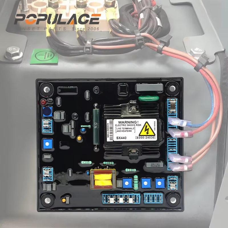
Prove genset speed control with staged load testing
After the no-load settings are stable, test the genset speed control under controlled load. Use the site commissioning plan and the engine manufacturer’s load-step limits. A typical record includes no-load, intermediate, and higher approved load points, plus a controlled step up and step down. At every point, capture frequency, voltage, kW, engine behavior, alarms, and recovery trend.
| Observation | Likely direction to investigate |
|---|---|
| Slow recovery after a load increase | Confirm fuel delivery and actuator travel, then review gain or response settings within the manual. |
| Repeated hunting at steady load | Check sensor noise, linkage, grounding, and excessive gain; restore the last stable setting before further tests. |
| Frequency changes with vibration | Inspect speed pickup mounting, wiring, shielding, and mechanical drive condition. |
| Uneven load share in parallel | Stop independent adjustments and verify load-share signals, droop coordination, and switchgear procedure. |
Do not judge the tune from frequency alone. Voltage response, exhaust condition, abnormal vibration, and protection events matter too. If the controller reaches a limit, an actuator saturates, or an alarm occurs, stop the test and correct the underlying fault rather than masking it with another governor parameter.
Troubleshooting limits and documentation
A governor genset should be returned to service only after the settings are documented. Record the original and final values, instrument readings, load points, ambient conditions, controller software version, alarm history, and the technician’s approval. Attach configuration files where available. This makes the next maintenance visit safer and helps distinguish a new fault from a changed calibration.
Do not perform live adjustments when there is an unresolved protection fault, unstable frequency, uncertain operating mode, unapproved parallel operation, or no safe way to apply and remove load. Likewise, avoid treating a genset electronic governor as a stand-alone part: a governor controller, actuator, speed sensor, fuel system, engine, and alternator work as one system.
Final checklist
- Correct model data and backed-up settings confirmed.
- Mechanical, fuel, sensor, and DC-supply checks completed.
- Rated speed set only with the approved reference adjustment.
- Stability assessed with controlled load changes.
- Droop or isochronous mode verified for the actual operating configuration.
- Load-test readings and final settings documented before release.
Careful calibration protects more than frequency accuracy. It gives the governor genset a stable operating baseline and gives the maintenance team evidence for future troubleshooting. When controller-specific limits are unclear, use the manufacturer’s documentation or obtain qualified commissioning support before making another change.






