Detailed Product Description
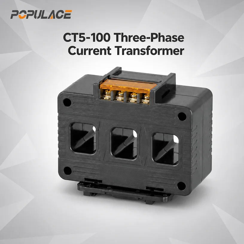
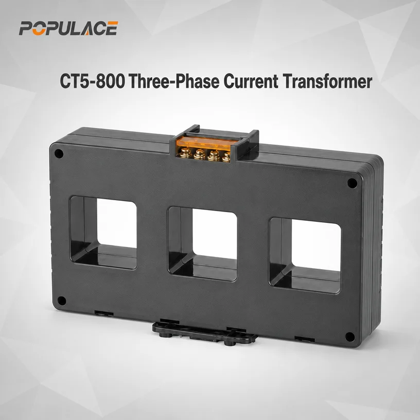
The CT5 series occupies a specific niche in the current transformer landscape: it consolidates three separate phase sensors into one molded housing. In a conventional panel layout, measuring three-phase current requires three individual CTs, each with its own mounting footprint, secondary wiring, and terminal connections. The CT5 three phase current transformer replaces that arrangement with a single device that straddles the three-phase conductor set, reducing panel space requirements and wiring complexity simultaneously .
The physical design reflects its intended installation environment. The through-core apertures are spaced to align with standard molded case circuit breaker (MCCB) terminal layouts, particularly the NSX and NXM series referenced in manufacturer documentation . This means the CT5 can be positioned directly at the output terminals of a breaker, capturing current signals at the point where they are most relevant for protection and metering. The device accepts both copper busbars and insulated cables through its cores, providing flexibility in panel wiring approaches .
The “lead wire” designation in the product title refers to the secondary output configuration. Rather than screw terminals requiring separate wire preparation, the CT5 series provides factory-attached leads that connect directly to the measuring instrument or controller. This detail matters in high-volume panel assembly: eliminating terminal preparation and torque verification for each secondary connection reduces assembly time and removes a potential point of connection failure. The lead length and termination style can be specified according to the target device’s input requirements.
The three-in-one architecture introduces a technical consideration that single-phase CTs do not present: phase-to-phase magnetic interaction. When three current-carrying conductors pass through adjacent cores in close proximity, the magnetic fields can influence neighboring phase measurements. The CT5 housing addresses this through internal shielding and core placement that maintains phase isolation within the device’s accuracy specification . For panel builders, this means the three phase current transformer delivers phase current readings that can be used for individual phase monitoring, unbalanced load detection, and total power calculations without requiring separate calibration for cross-phase interference.
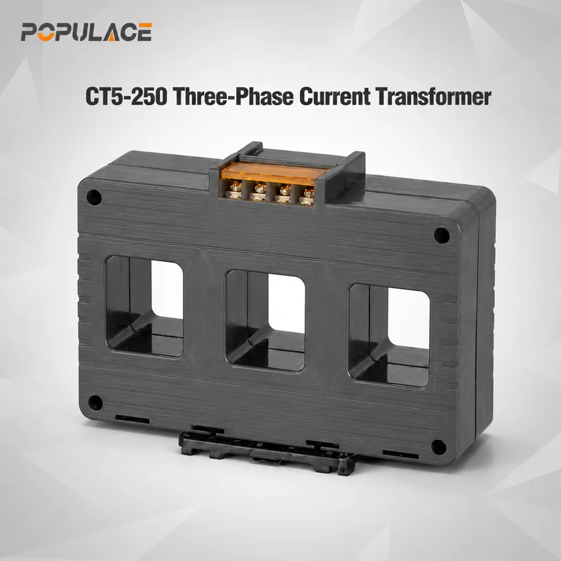
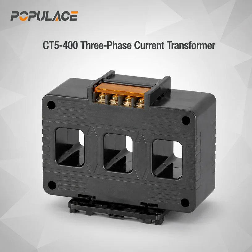
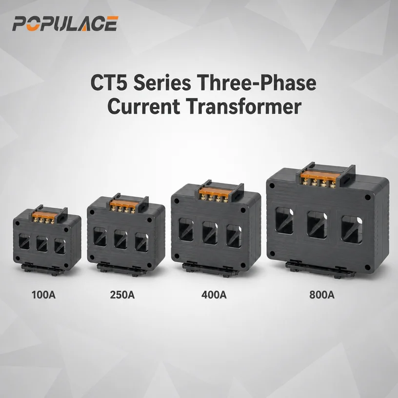
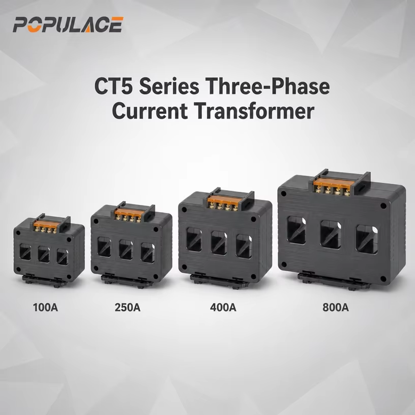
The CT5-100, CT5-250, CT5-400, and CT5-800 model designations correspond to the maximum primary current rating in amperes. Within each frame, multiple ratio options are available—for example, the CT5-100 frame supports 60/5, 100/5, 125/5, and 150/5 ratios . The CT5-800 frame extends coverage to 800A primary, accommodating larger generator output circuits and main feeder applications. Accuracy class options include 0.5 for metering applications and 1.0 or 3 for indication and general monitoring .
Technical Specifications
| Rated test voltage |
3Kv AC (1 min) |
| Rated short-time thermal current (Ith) |
60In |
| 60In Rated dynamic current (Idyn) |
2.5Ith |
| Rated voltage (Um) |
0.72Kv AC |
| Continuous overload (Id) |
1.2In |
| Operating temperature |
-10℃ to 50℃ |
| Housing self-extinguishing class |
VO |
| Safety factor |
FS 5 |
| Secondary current |
5A/1A |
Technical Advantages
Panel Space Reduction. Three single-phase CTs require three mounting positions, three sets of secondary wiring, and three terminal blocks. The CT5 three phase current transformer consolidates these into one device, freeing panel space for controllers, meters, and other components. In generator control panels where DIN rail real estate is constrained, this reduction directly affects layout flexibility .
Wiring Complexity Reduction. Each secondary connection point is a potential source of error, loose termination, or wiring misidentification. By integrating three phases into one housing with factory-attached leads, the CT5 reduces the number of field wiring operations per metering point. For panel builders producing repeat assemblies, this translates to shorter build times and fewer inspection touchpoints.
Consistent Phase Alignment. When three separate CTs are mounted individually, slight variations in conductor positioning within each core can introduce phase-to-phase measurement discrepancies. The CT5 housing fixes the relative position of the three cores, promoting consistent coupling across phases. This consistency supports accurate unbalanced load calculations and phase-specific monitoring.
High-Permeability Core Options. The availability of nickel steel or nanocrystalline cores provides design flexibility. Nanocrystalline cores offer higher permeability and lower core loss than conventional silicon steel, supporting accuracy at lower current levels and reducing phase error . For generator panels that must meter accurately across a wide load range—from light standby loads to full prime power output—this material choice affects measurement reliability.
Integrated Hinged Terminal Cover. The built-in terminal cover provides protection against accidental contact with secondary connections while remaining attached to the housing, avoiding the lost-cover problem common with separate components .
Applications
Diesel Generator Control Panels. The primary application for this three phase current transformer is current measurement in genset control and metering circuits. Generator controllers require three-phase current inputs for load monitoring, overcurrent protection, and power calculations. The CT5 compact housing fits the space constraints typical of genset panel layouts.
Multi-Loop Current Monitoring. The CT5 series is commonly paired with multi-circuit monitoring devices (such as AMC16 series) for branch circuit metering in distribution panels . The three-in-one design aligns with the multi-channel inputs of these monitoring devices, simplifying the wiring between CT and meter.
Molded Case Circuit Breaker Outputs. The aperture spacing designed for MCCB terminal dimensions allows the CT5 to mount directly at breaker outputs . This positioning captures current at the feeder origination point, which is preferred for protection coordination and feeder-level metering.
Energy Management and Sub-Metering. Class 0.5 accuracy supports energy allocation and sub-billing applications where measurement error affects cost distribution. The three-phase consolidated measurement simplifies the data acquisition architecture for building energy management systems.
Power Factor and Load Management. CTs provide the current signal for power factor controllers and load-shedding logic. The CT5’s consistent phase alignment supports reliable three-phase power calculations used in automated load management decisions.
FAQ
Q: What does “three-in-one” mean for a current transformer?
A: A three-in-one CT integrates three separate current sensing cores into a single housing. Instead of installing three individual CTs—one per phase—the device captures all three phase currents simultaneously. This reduces panel space, wiring, and component count .
Q: Can the CT5 series be used with both busbars and cables?
A: Yes. The through-core apertures accept both copper busbars and insulated cables. The aperture dimensions are sized to accommodate standard busbar cross-sections and cable diameters within the model’s current rating .
Q: What is the difference between the CT5-100, CT5-250, CT5-400, and CT5-800 models?
A: The model suffix indicates the maximum primary current rating: 100A, 250A, 400A, and 800A respectively. Within each frame, multiple ratio options are available. Select the frame based on the maximum expected load current, with normal operating current ideally falling within 60–80% of the CT primary rating for optimal metering resolution.
Q: What secondary output options are available?
A: The CT5 series supports 5A and 1A standard secondary outputs, as well as mA-level or voltage signal outputs depending on configuration . The appropriate output depends on the input requirements of the connected meter, controller, or monitoring device.
Q: How does accuracy class 0.5 differ from class 1.0?
A: Accuracy class defines the maximum permissible ratio and phase error at rated current. Class 0.5 has tighter error limits than class 1.0, making it suitable for revenue metering and billing applications. Class 1.0 is generally adequate for indication, monitoring, and protection functions where billing-grade precision is not required.
Q: Does the three-in-one design affect phase measurement independence?
A: The CT5 housing is designed to maintain phase isolation within the specified accuracy class. However, when installing the device, the primary conductors should be centered within their respective apertures and routed to minimize external magnetic field interference. In high-current applications, maintaining the specified clearance between the CT and adjacent current-carrying conductors supports measurement stability .


 EN